Agriculture
About Us
Sagar group of companies, Est. in 1988, a reputed group have promoted Sagar Polymers. The company was established in the year 2000 and has gained high reputation in the field of manufacturing different types of PVC, CPVC, HDPE, PPR - pipes, fittings & hoses and Drip & Sprinkler Irrigation Systems etc. in a wide range of quality and sizes.
Read MoreContact Info
- Plot No.: 2819-2826, Lodhika G.I.D.C., Metoda, Dist.: Rajkot - 360 021, Gujarat, India.
- +91 28272 34600
- info@sagarpolymers.com
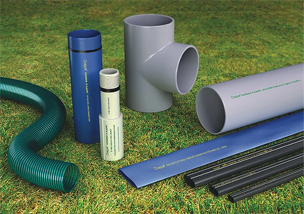
Applications
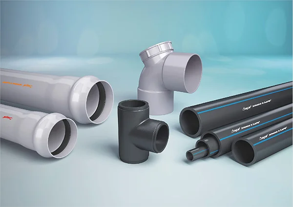
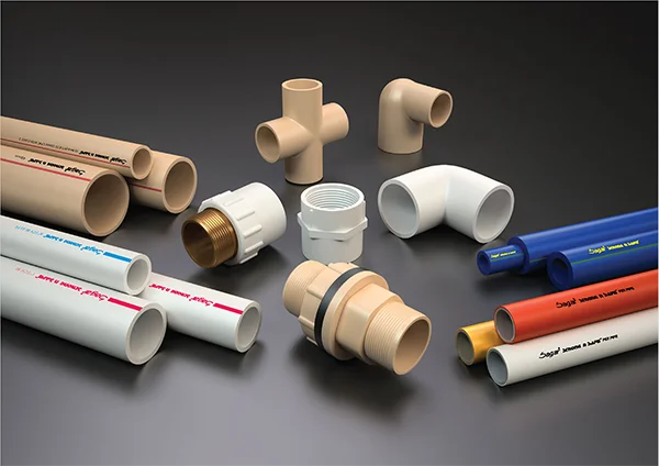
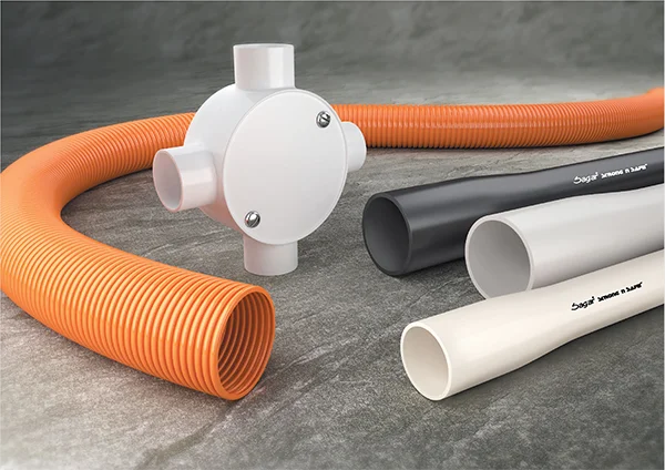
Various Products of Sagar
Trusted Best Company...
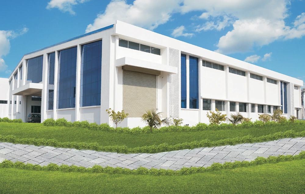
About Sagar Polytechnik Ltd.
Sagar group of companies, Est. in 1988, a reputed group have promoted Sagar Polymers. The company was established in the year 2000 and has gained high reputation in the field of manufacturing different types of PVC, CPVC, HDPE, PPR - pipes, fittings & hoses and Drip & Sprinkler Irrigation Systems etc. in a wide range of quality and sizes.
+
Years In Business
+
Products
+
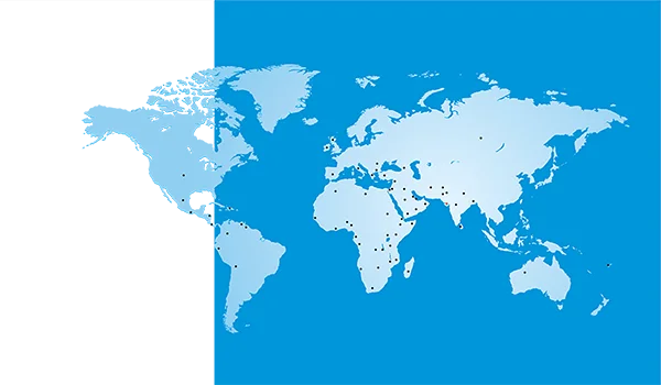
Exports Countries
+
Our Main Applications
What we do...
Explore Our Products
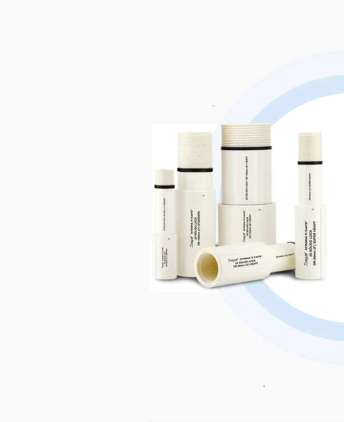
Agriculture
uPVC Column Pipes
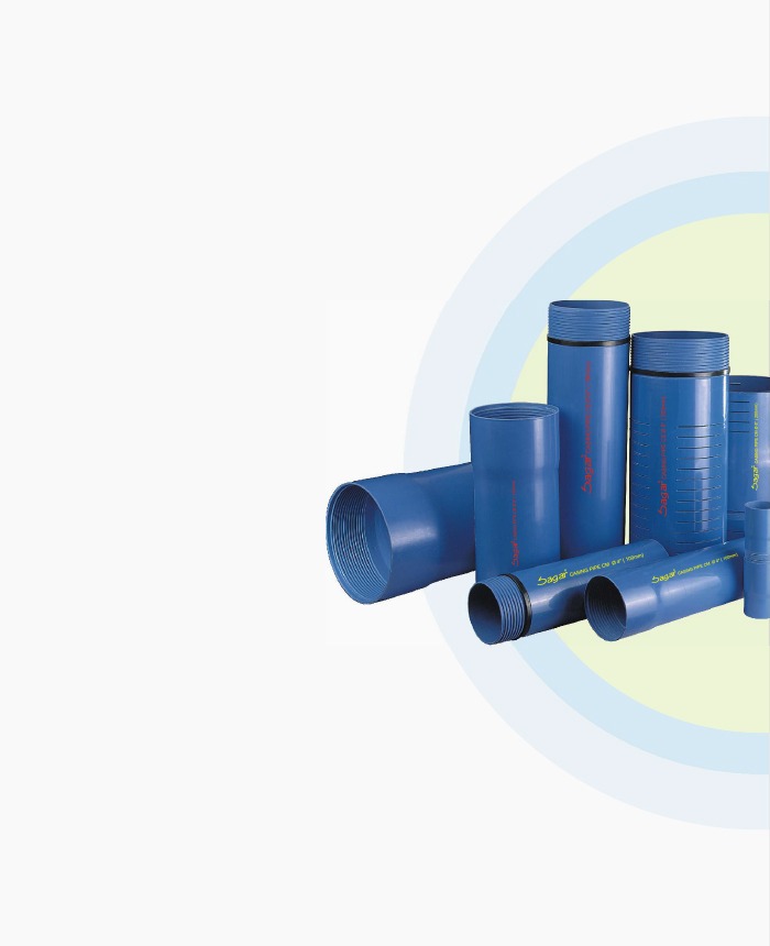
Agriculture
uPVC Casing Pipes
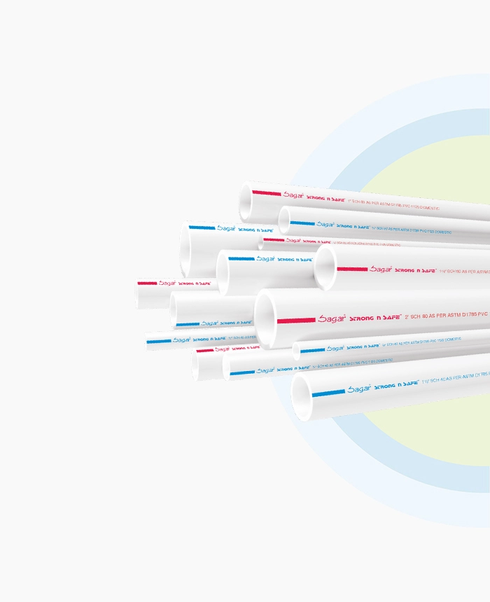
Plumbing
UPVC Pipes
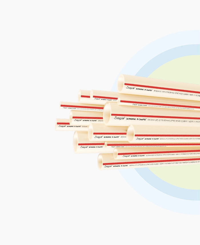
Plumbing
CPVC Pipes
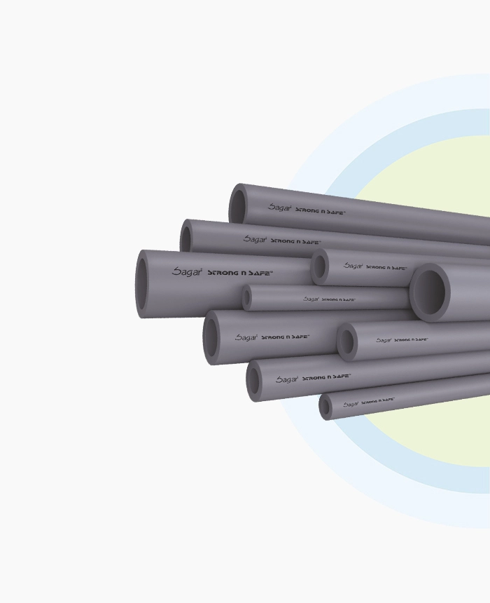
Plumbing
CPVC 40 & 80 Pipes
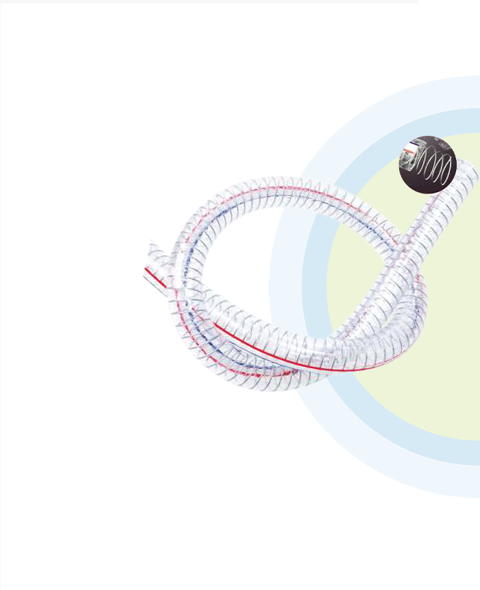
Industrial
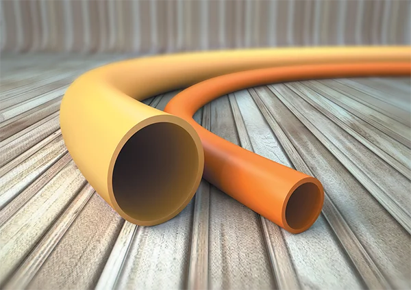
Steel wire hose
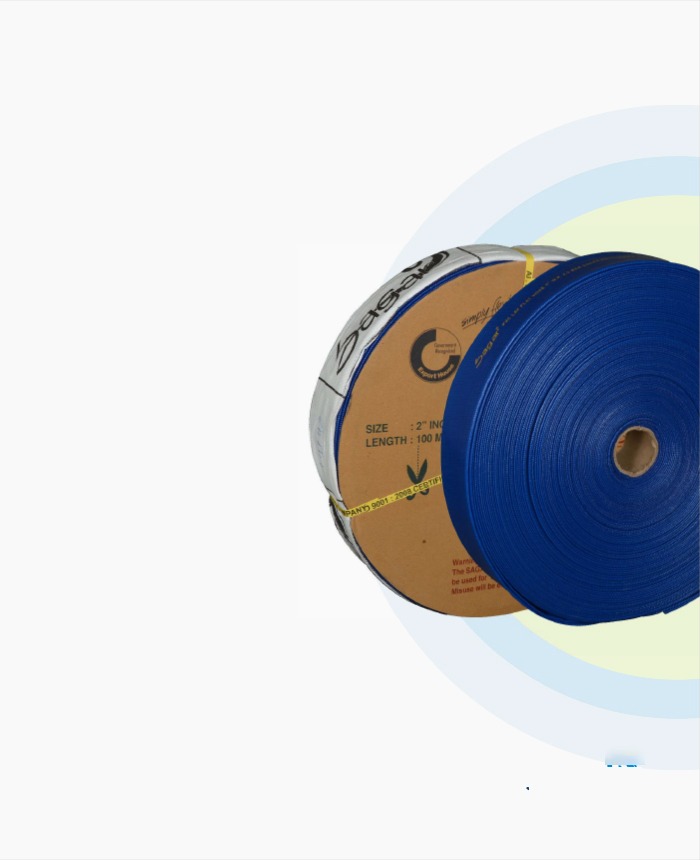
Agriculture
PVC lay flat hose
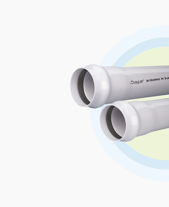
Water Distribution
uPVC Ringfit Pressure Pipe
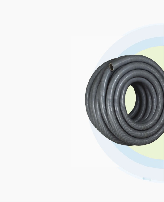
Agriculture
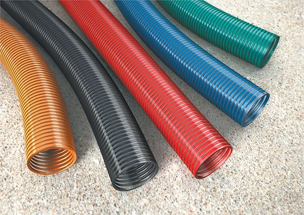
PVC Suction hose
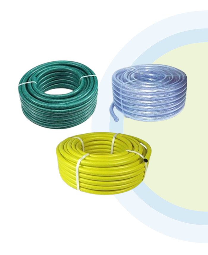
Industrial
PVC GARDEN HOSE
01
Our Vision
The company foresees to become a pioneer in innovating newer products, creating brand value, enhance quality of products and thereby increasing its market share.
View Details 
02
Our Presence
Sagar group of companies is a business empire built with a core purpose to improve people’s lives by manufacturing reliable products that enable efficient transportation of water – one of the five elements of nature.
View Details 


Request a Quote