Mpa = Mega Pascal 1Mpa=10kg/cm² 1kg/cm²=14.223343PSI.
Note
- Non Standard wall thickness, length and color can also be offered If desired
- Pipes can also be offered as per DIN 8062, ISO 4422-2, BS 3505/6
SAGAR® uPVC Plumbing Pipes Temperature Pressure De-Rating Factor:
The operating pressure of uPVC pipe will be reduced as the operating temperature increases above 23°C (73° F).To calculate this reduction, multiply the operating pressure with the correction factors shown below at a operating temperature of system:
| Operating Temp. °C(F) |
23°(73) |
27°(80) |
32°(90) |
38°(100) |
43°(110) |
49°(120) |
54°(130) |
60°(140) |
| uPVC |
100% |
90% |
75% |
62% |
50% |
40% |
30% |
22% |
Physical Properties of PVC Materials
| Property |
Units |
PVC |
ASTM No. |
| Specific Gravity |
g/cc |
1.41 -1.46 |
D 792 |
| Tensile Strength (73°F) |
PSI |
7,200 |
D 638 |
| Modulus of Elasticity in Tension (73°F) |
PSI |
4,60,000 |
D 638 |
| Flexural Strength (73°F) |
PSI |
13,200 |
D 790 |
| Izod Impact (notched at 73°F) |
ft lb/in |
0.65 |
D 256 |
| Hardness (Durometer D) |
--- |
80±3 |
D 2240 |
| Hardness (Rockwell R) |
--- |
110-120 |
D 785 |
| Compressive Strength (73°F) |
PSI |
9,000 |
D 695 |
| Hydrostatic Design Stress |
PSI |
2,000 |
D 1598 |
| Coefficient of Linear Expansion |
in/in/°F |
3.1X10⁻⁵ |
D 696 |
| Heat Deflection Temperature at 66psi |
degrees °F |
165 |
D 648 |
| Coefficient of Thermal Conductivity |
BTU/hr/sq.ft/°F/in |
1.2 |
D 177 |
| Specific Heat |
BTU/F/lb |
0.25 |
D 2766 |
| Limiting Oxygen Index |
% |
43 |
D 2863 |
| Water Absorption (24hrs at 73°F) |
% weight gain |
0.05 |
D 570 |
| Cell Classification-Pipe |
--- |
12454-B |
D 1784 |
| Cell Classification-Fittings |
--- |
12454-B |
D 1784 |
Joint Curing
| Recommended Initial Set Times |
TEMP.
RANGE (°C) |
Pipe Sizes
½" to 1¼"
15 to 32mm |
Pipe Sizes
½" to 3"
40 to 80mm |
Pipe Sizes
4" to 3"
100 to 200mm |
Pipe Sizes
10" to 12"
250 to 300mm |
| 15.5°C - 37.7°C |
15min. |
30min. |
1hrs. |
2hrs. |
| 4.4°C - 15.5°C |
1hrs. |
2hrs. |
4hrs. |
8hrs. |
| Recommended Initial Cure Times |
| 15.5°C - 37.7°C |
6hrs. |
12hrs. |
24hrs. |
48hrs. |
| 4.4°C - 15.5°C |
12hrs. |
24hrs. |
48hrs. |
96hrs. |
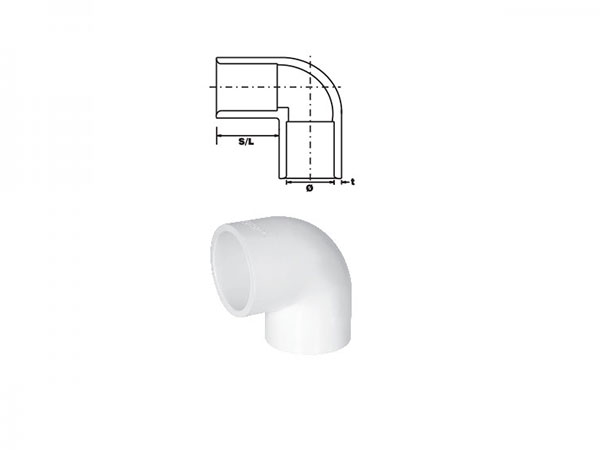
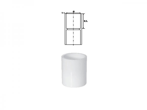
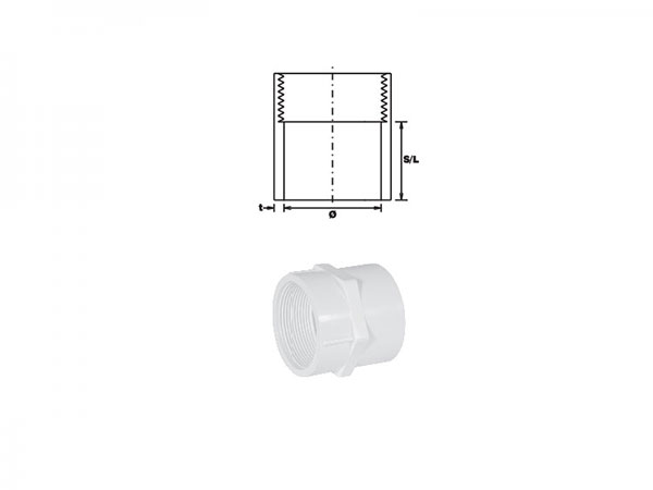
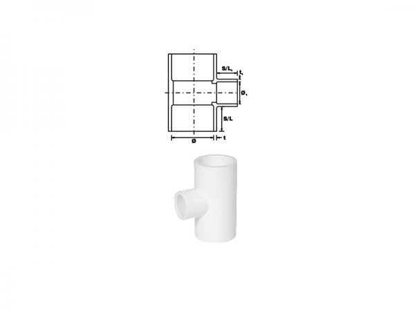
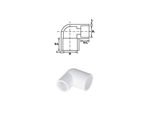
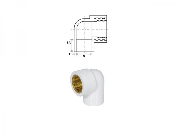
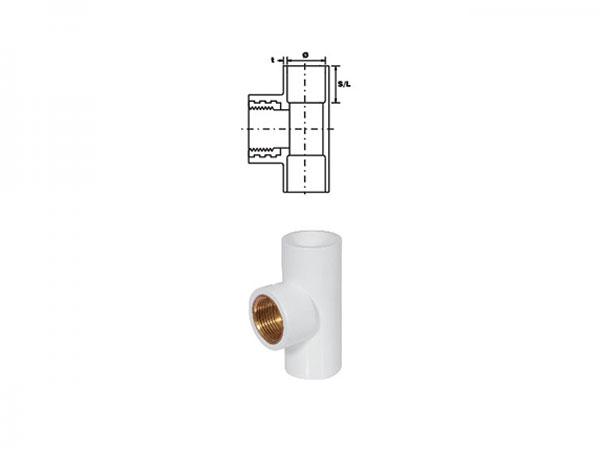
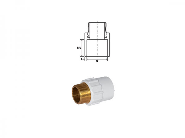
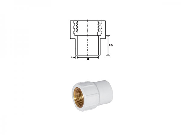
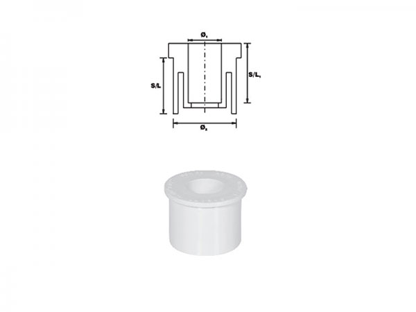
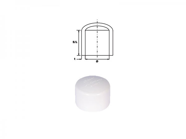
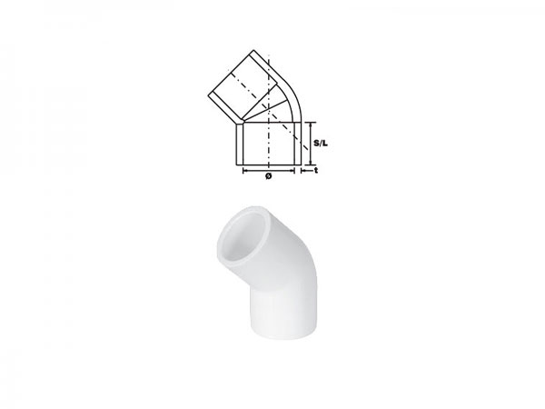
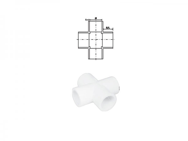
Technical Specifications of Fittings
| Size (Inch) |
Thickness
' t '
(Min.) |
Socket Length
'S/L'
(Min.) |
Socket
I.D.
'Ø ' |
Thread (TPI) |
| Min. |
Max. |
| ½ |
0.109 |
0.688 |
0.832 |
0.852 |
14 |
| 3/4 |
0.113 |
0.719 |
1.042 |
1.062 |
14 |
| 1 |
0.133 |
0.875 |
1.305 |
1.330 |
11 |
| 1¼ |
0.140 |
0.938 |
1.650 |
1.675 |
11 |
| 1½ |
0.145 |
1.094 |
1.888 |
1.918 |
11 |
| 2 |
0.154 |
1.156 |
2.363 |
2.393 |
11 |
| 2½ |
0.203 |
1.750 |
2.861 |
2.896 |
11 |
| 3 |
0.216 |
1.875 |
3.484 |
3.524 |
11 |
| 4 |
0.237 |
2.000 |
4.482 |
4.527 |
11 |
| 6 |
0.280 |
3.000 |
6.603 |
6.658 |
11 |
Note
- All Dimensions are in inch
- 1 inch = 25.4 mm
- Please contact at your nearest place for available size for particular type of fitting.
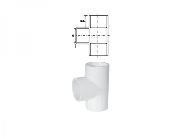
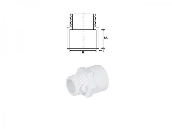
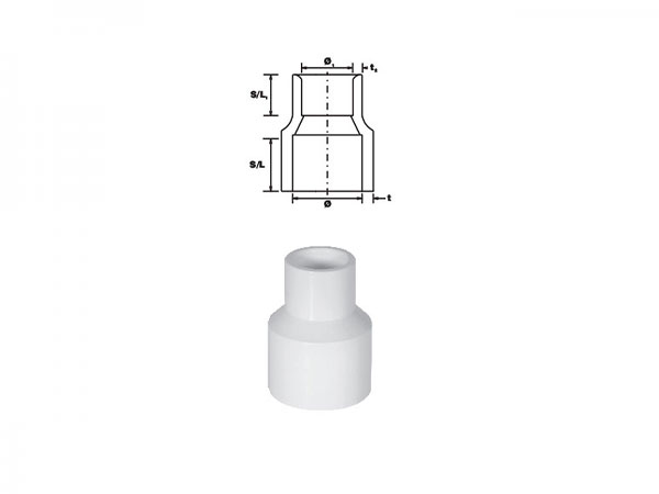
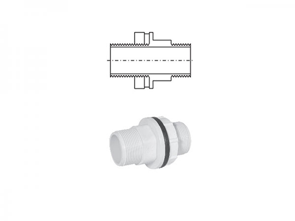
uPVC Fittings Specifications
SAGER® uPVC Plumbing Fittings Technical Specifications:
| Size (Inch) |
Thickness
' t '
(Min.) |
Thickness
' t1 '
(Min.) |
Thickness
' t2 '
(Min.) |
Socket Length
'S/L'
(Min.) |
Socket Length
'S/L1'
(Min.) |
Socket
I.D.
'Ø ' |
Socket
I.D.
'Ø1 ' |
R. Bushing
O.D.
'Ø2 ' |
| Min. |
Max. |
Min. |
Max. |
Min. |
Max. |
| ¾ x ½ |
0.113 |
0.109 |
0.136 |
0.719 |
0.688 |
1.042 |
1.062 |
0.832 |
0.852 |
1.046 |
1.057 |
| 1 x ½ |
0.133 |
0.109 |
0.136 |
0.875 |
0.688 |
1.305 |
1.330 |
0.832 |
0.852 |
1.310 |
1.323 |
| 1 x ¾ |
0.133 |
0.113 |
0.141 |
0.875 |
0.719 |
1.305 |
1.330 |
1.042 |
1.062 |
1.310 |
1.323 |
| 1¼ x ½ |
0.140 |
0.109 |
0.136 |
0.938 |
0.688 |
1.650 |
1.675 |
0.832 |
0.852 |
1.655 |
1.668 |
| 1¼ x ¾ |
0.140 |
0.133 |
0.141 |
0.938 |
0.719 |
1.650 |
1.675 |
1.042 |
1.062 |
1.655 |
1.668 |
| 1¼ x 1 |
0.140 |
0.133 |
0.166 |
0.938 |
0.875 |
1.650 |
1.675 |
1.305 |
1.330 |
1.655 |
1.668 |
| 1½ x ½ |
0.145 |
0.109 |
0.136 |
1.094 |
0.688 |
1.888 |
1.918 |
0.832 |
0.852 |
1.894 |
1.910 |
| 1½ x ¾ |
0.145 |
0.113 |
0.141 |
1.094 |
0.719 |
1.888 |
1.918 |
1.042 |
1.062 |
1.894 |
1.910 |
| 1½ x 1 |
0.145 |
0.133 |
0.166 |
1.094 |
0.875 |
1.888 |
1.918 |
1.305 |
1.330 |
1.894 |
1.910 |
| 1½ x 1¼ |
0.145 |
0.140 |
0.175 |
1.094 |
0.938 |
1.888 |
1.918 |
1.650 |
1.675 |
1.894 |
1.910 |
| 2 x ½ |
0.154 |
0.109 |
0.136 |
1.156 |
0.688 |
2.363 |
2.393 |
0.832 |
0.852 |
2.369 |
2.385 |
| 2 x ¾ |
0.154 |
0.113 |
0.141 |
1.156 |
0.719 |
2.363 |
2.393 |
1.042 |
1.062 |
2.369 |
2.385 |
| 2 x 1 |
0.154 |
0.133 |
0.166 |
1.156 |
0.875 |
2.363 |
2.393 |
1.305 |
1.330 |
2.369 |
2.385 |
| 2 x 1¼ |
0.154 |
0.140 |
0.175 |
1.156 |
0.938 |
2.363 |
2.393 |
1.650 |
1.675 |
2.369 |
2.385 |
| 2 x 1½ |
0.154 |
0.145 |
0.181 |
1.156 |
1.094 |
2.363 |
2.393 |
1.888 |
1.918 |
2.369 |
2.385 |
| 2½ x 2 |
0.203 |
0.154 |
0.193 |
1.750 |
1.156 |
2.861 |
2.896 |
2.363 |
2.393 |
2.868 |
2.887 |
| 3 x 1½ |
0.216 |
0.145 |
0.181 |
1.875 |
1.094 |
3.484 |
3.524 |
1.888 |
1.918 |
3.492 |
3.513 |
| 3 x 2 |
0.216 |
0.154 |
0.193 |
1.875 |
1.156 |
3.484 |
3.524 |
2.363 |
2.393 |
3.492 |
3.513 |
| 3 x 2½ |
0.216 |
0.203 |
0.254 |
1.875 |
1.750 |
3.484 |
3.524 |
2.861 |
2.896 |
3.492 |
3.513 |
| 4 x 2 |
0.237 |
0.154 |
0.193 |
2.000 |
1.156 |
4.482 |
4.527 |
2.363 |
2.393 |
4.491 |
4.515 |
| 4 x 2½ |
0.237 |
0.203 |
0.254 |
2.000 |
1.750 |
4.482 |
4.527 |
2.861 |
2.896 |
4.491 |
4.515 |
| 4 x 3 |
0.237 |
0.216 |
0.270 |
2.000 |
1.875 |
4.482 |
4.527 |
3.484 |
3.524 |
4.491 |
4.515 |
| 6 x 3 |
0.280 |
0.216 |
0.270 |
3.000 |
1.875 |
6.603 |
6.658 |
3.484 |
3.524 |
6.614 |
6.643 |
| 6 x 4 |
0.280 |
0.237 |
0.296 |
3.000 |
2.000 |
6.603 |
6.658 |
4.482 |
4.527 |
6.614 |
6.643 |
Note
- All Dimensions are in inch.
- 1 inch = 25.4 mm
- Please contact at your nearest place for available size for particular type of fitting.
uPVC Fittings Pressure Rating
SAGER® uPVC Plumbing Fittings Pressure Rating @ 73°F (23°C) Schedule 40 & Schedule 80:
| |
Schedule 40 (kg/cm²) |
Schedule 80 (kg/cm²) |
| Nominal Size Sch 40-80 |
Pipe¹ |
Solvent Cemented
Joint |
Standard Threaded
Joint |
Pipe¹ |
Solvent Cemented
Joint |
Standard Threaded
Joint |
| ½ |
15 |
42.19 |
25.31 |
21.09 |
59.76 |
35.85 |
29.88 |
| 3/4 |
20 |
33.75 |
20.24 |
16.87 |
48.51 |
29.10 |
24.25 |
| 1 |
25 |
31.64 |
18.98 |
15.81 |
44.29 |
26.57 |
22.14 |
| 1¼ |
32 |
26.01 |
15.60 |
13.00 |
36.56 |
21.93 |
17.27 |
| 1½ |
40 |
23.20 |
13.92 |
11.60 |
33.04 |
19.82 |
16.52 |
| 2 |
50 |
19.69 |
11.81 |
9.84 |
28.12 |
16.87 |
14.06 |
| 2½ |
65 |
21.09 |
12.65 |
10.54 |
29.53 |
17.71 |
14.76 |
| 3 |
80 |
18.28 |
10.96 |
9.13 |
26.01 |
15.60 |
13.00 |
| 4 |
100 |
15.47 |
9.28 |
7.73 |
22.50 |
13.49 |
11.24 |
| 6 |
150 |
12.66 |
7.59 |
6.32 |
19.69 |
11.81 |
9.84 |
| 8 |
200 |
11.25 |
6.74 |
5.62 |
17.57 |
10.54 |
8.78 |
| 10 |
250 |
9.84 |
5.90 |
4.92 |
16.17 |
9.70 |
8.08 |
| 12 |
300 |
9.14 |
5.48 |
4.56 |
16.17 |
9.70 |
8.08 |
Mpa = Mega Pascal 1Mpa=10kg/cm² 1kg/cm²=14.223343PSI.
- 1. Water pressure Rating at 73 F (23 C) for Schedule 40 and Schedule 80 Plastic Pipe, ASTM 1785 for PVC
- 2. Threading of Schedule 40 plastic pipe is not permitted. Recommended pressures apply to molded fittings only
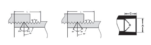
uPVC Fittings ANSI & BSP Standard
American National Standard Taper Pipe Threads (NPT) ANSI Standard B1.20.1 ASTM Standard F 1498
| Nominal Size |
Threads per
in. |
Effective Thread
Lenght (L) |
Pitch of Thread
(P) |
| (mm) |
(inch) |
| 15 |
½ |
14 |
0.5337 |
0.07143 |
| 20 |
3/4 |
14 |
0.5457 |
0.07143 |
| 25 |
1 |
11½ |
0.6828 |
0.08696 |
| 32 |
1¼ |
11½ |
0.7068 |
0.08696 |
| 40 |
1½ |
11½ |
0.7235 |
0.08696 |
| 50 |
2 |
11½ |
0.7565 |
0.08696 |
| 65 |
2½ |
8 |
1.1375 |
0.12500 |
| 80 |
3 |
8 |
1.2000 |
0.12500 |
| 100 |
4 |
8 |
1.3000 |
0.12500 |
BSP ISO 7/1 Parellel Threads
| Nominal Size |
Threads per
in. |
Effective Thread
Length (L) |
Pitch of Thread
(P) |
| (mm) |
(inch) |
| 15 |
½ |
14 |
13.152 |
1.8143 |
| 20 |
3/4 |
14 |
14.514 |
1.8143 |
| 25 |
1 |
11 |
16.714 |
2.3091 |
| 32 |
1¼ |
11 |
19.050 |
2.3091 |
| 40 |
1½ |
11 |
19.050 |
2.3091 |
| 50 |
2 |
11 |
23.378 |
2.3091 |
| 65 |
2½ |
11 |
26.698 |
2.3091 |
| 80 |
3 |
11 |
29.873 |
2.3091 |
| 100 |
4 |
11 |
35.791 |
2.3091 |
Support Spacing for uPVC Pipe
Adequate supports for any piping system is a matter of great importance. In practice, support spacings are a function of pipe size operating temperatures, the location of heavy valves or fittings and the mechanical properties of the pipe material.
To ensure the satisfactory operation of a uPVC piping system, the location and type of hangers should be carefully considered. Hangers should not compress, distort, cut or abrade the piping.
All piping should be supported with an approved hanger at intervals sufficiently close to maintain correct pipe alignment and to prevent sagging or geade reversal. Pipe should also be supported at all branch ends and at all changes of direction. Support trap arms as close as possible to the trap. In keeping with good plumbing practices support and brace all closet bends and fasten closet flanges.
- (1) Concentrated loads should be supported directly so as to eliminate high stress concentrations. Should this be impractical then the pipe must be supported immediately adjacent to the load.
- (2) In systems where large fluctuations in temperature occur, allowances must be made for expansion and contraction of the piping system. Since changes in direction in the system are usually sufficient to allow for expansion and contraction hangers must be placed so as not to restrict this movement.
- (3) Since plastic pipe expands or contracts approximately five times greater than those of steel, hangers should not restrict this movement
- (4) Hangers should provide as much bearing surface as possible. To prevent damage to the pipe, file smooth any sharp edges or burrs on the hangers or supports.
- (5) Support spacing for horizontal piping systems is determined by the maximum operating temperature the system will encounter. The piping should be supported on uniform centers with supports that do not restrict the axial movement.
- (6) For vertical lines, it is recommended that an engineer should design the vertical supports according to the vertical load involved.
Recommended Support Spacing Scheule 40 & Scheule 80 (in feet)
| Nominal Size Sch 40-80 |
Temperature (°C) Scheule 40 |
Temperature (°C) Scheule 80 |
| (inch) |
(mm) |
15.5 |
26.6 |
37.7 |
48.8 |
60 |
15.5 |
26.6 |
37.7 |
48.8 |
60 |
| ½ |
15 |
4½ |
4½ |
4 |
2½ |
2½ |
5 |
4½ |
4½ |
3 |
2½ |
| 3/4 |
20 |
5 |
4½ |
4 |
2½ |
2½ |
5½ |
5 |
4½ |
3 |
2½ |
| 1 |
25 |
5½ |
5 |
4½ |
3 |
2½ |
6 |
5½ |
5 |
3½ |
3 |
| 1¼ |
32 |
5½ |
5½ |
5 |
3 |
3 |
6 |
6 |
5½ |
3½ |
3 |
| 1½ |
40 |
6 |
5½ |
5 |
3½ |
3 |
6½ |
6 |
5½ |
3½ |
3½ |
| 2 |
50 |
6 |
5½ |
5 |
3½ |
3 |
7 |
6½ |
6 |
4 |
3½ |
| 2½ |
65 |
6½ |
6 |
5½ |
4 |
3 |
7½ |
7½ |
6½ |
4½ |
4 |
| 3 |
80 |
7 |
7 |
6 |
4 |
3½ |
8 |
7½ |
7 |
4½ |
4 |
| 4 |
100 |
7½ |
7 |
6½ |
4½ |
4 |
9 |
8½ |
7½ |
5 |
4½ |
| 6 |
150 |
8½ |
8 |
7½ |
5 |
4½ |
10 |
9½ |
8½ |
6½ |
5½ |
| 8 |
200 |
9½ |
9 |
8½ |
5½ |
5 |
11 |
10 |
9½ |
7½ |
6 |
| 10 |
250 |
10½ |
9½ |
9 |
6½ |
5½ |
12½ |
11 |
10½ |
8 |
7 |
| 12 |
300 |
12 |
10½ |
9½ |
7 |
6 |
13 |
12 |
10½ |
7½ |
6½ |
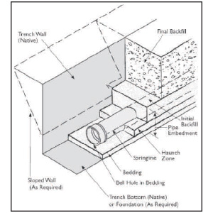
Underground Installation
uPVC pipes and fittings can be installed underground, Since these piping systems are flexible systems, proper attention should be given to burial conditions. The stiffness of the piping system is affected by sidewall support, soil compaction, and the condition of the trench, Trench bottoms should be smooth and regular in either undisturbed soil or a layer of compacted backfill. Pipe must lie evenly on this surface throughout the entire length of its barrel, Excavation, bedding and backfill should be in accordance with the provision of the local Plumbing Code having jurisdiction.
Trenching
The following trenching and burial procedures should be used to protect the piping system.
- 1 The trench should be excavated to ensure the sides will be stable under all working conditions.
The Trench should be wide enough to provide adequate room for the following:
- A Jointing the pipe in the trench
- B Snaking the pipe from side or side to compensate for expansion and contraction.
- C Filling and compacting the side fills.
- The space between the pipe and trench wall must be wider than the compaction of the backfill. Minimum
width shall not be less than the greater of either the pipe outside diameter plus 16 inches or the pipe
outside diameter times 1.25 pius 12 inches. Trench width may be different if approved by the design engineer
- 2 The trench bottom should be smooth, free of rocks and debris, continuous, and provide uniform support. If ledge roce, hardpan or large boulders are encountered, the trench bottom should be padded with bedding of compacted granular material to a thickness of at least 4 inches. Foundation bedding shuold be installed as required by the enginner.
- 3 Trench depth is determine by the pipe's service requirements. Plastic pipe should always be installed at least below the frost level. The minimum cover for lines subject to heavy overhead traffic is 24 inches.
- 4 A smooth, trench bottom is necessary to support the pipe over its entire lengh on firm stable material. Blocking should be used charge pipe grade or to intermittently support pipe over low section in the trench.
Bedding and Backfilling
- 1. Even though sub-soil conditions vary widely from place to place, the pipe backfill should be stable and provide protection for the pipe.
- 2. The pipe should be surrounded with a granular material which is easily worked around the sides of the pipe Backfilling should be performed in layer of 6 inch with each layer being sufficiently compacted to 85% to 95% compaction.
- 3. A mechanical tamper is recommended for compacting sand and gravel backfill which contain a significant proportion of fine grained material, such as silt and clay. If a tamper is not available, compacting should be done by hand.
- 4. The trench should be completely filled. The back fill should be placed and spread in fairly uniform layers to prevent any unfilled spaces or voids. Large rocks, stones, frozen clods, or other large debris should be removed. Heavy tampers or rolling equipment should only be used to consolidate only the final backfill.
Expansion and Contraction of uPVC Pipe
uPVC pipes, like other piping materials, undergo length changes as a result of temperature variations above and below the installation temperature. They expand and contract 4.5 to 5 times more than steel or iron pipe. The extent of the expansion - contraction depends upon the coefficient of linear expansion of piping material. The length of pipe between directional changes, and the temperature differential.
The coefficient of thermal expansion (Y) for uPVC is 3.1 x 10°in/in/°F
The amount of expansion or contraction can be calculated using the following formula:
ΔL = Y (T1-T2) x L ( - t2)
- ΔL = Dimensional change due to thermal expansion or contraction (inch)
- Y = Expansion coefficient ( in./in.°F)
- T1 - T2 =Temperature differential between the installation Temperature and the maximum or minimum system
- tempereture, whichever provides the greatest differential (°F)
- L = Length of pipe run between changes in direction (feet)
- ΔL = Dimensional change due to thermal expansion or contraction (inch)
- Y = Expansion coefficient ( in./in.°F) T1 - T2 = Temperature differential between the installation tempereture and the maximum or minimum system tempereture, whichever provides the greatest differential (°F)
- L = Length of pipe run between changes in direction (feet)
There are several ways to compensate for expansion and contraction. The most common methods are:
- 1. Expansion loops which consist of pipe and 90° elbows
- 2. Piston type expansion joints*
- 3. Flexible bends*
- 4. Bellows and rubber expansion joints*
* The manufacturers of these devices should be contacted to determine the suitability of their products for the specific application.
Expansion loops are a simple and convenient way to compensate for expansion and contraction when there is sufficient space for the loop in the piping system. A typical expansion loop design is
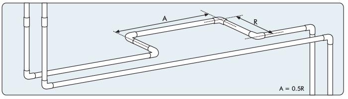
The length of leg "R" can be determined by using the following formula to ensure that it is long enough to absorb the expansion and contraction movement without damage. The length of leg "A" should be 1/2 the length of leg "R"
- R = 1.44 D Δ L
- R = Expansion loop leg lengh(feet)
- D = Normal outside diameter of pipe (in.)
(see table below)
- ΔL = Dimensional change due to thermal expansion or contraction (inch)
When installing the expansion loop, no rigid or restraining supports should be placed within the leg lengths of the loop. The loop should be installed as closely as possible to the mid-point between anchors. Piping support guides should restrict lateral movement and direct axial movement into the loop. Lastly, the pipe and fittings should be solvent cemented together, rather than using threaded connections.
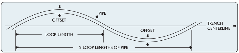
Compensation for expansion and contraction in underground application is normally achieved by snaking the pipe in the trench. Proper trenching and burial procedures must be followed to protect the piping system.
The table below shows recommended offsets and loop lengths for piping up to 2½" nominal siz
Loop Length
in Feet |
Max. Temp. Variation °F, Between Installation and Final Operation |
| 10° |
20° |
30° |
40° |
50° |
60° |
70° |
80° |
90° |
100° |
| Loop Offset in Inch |
| 20 |
3.0 |
3.5 |
4.5 |
5.0 |
6.0 |
6.5 |
7.0 |
7.0 |
8.0 |
8.0 |
| 50 |
7.0 |
9.0 |
11.0 |
13.0 |
14.0 |
15.5 |
17.0 |
18.0 |
19.0 |
20.0 |
| 100 |
13.0 |
18.0 |
22.0 |
26.0 |
29.0 |
31.5 |
35.0 |
37.0 |
40.0 |
42.0 |

Handaling & Storage
Handling
The pipe should be handled with reasonable care. Because thermoplastic pipe is much lighter in weight than metal pipe. There is sometimes a tendency to throw it around. This should be avoided.
The pipe should never be dragged or pushed from a truck bed. Pallets for pipe should be removed with a fork lift. Loose pipe can be rolled down timbers, as long as the pieces do not fall on each other or on any hard or uneven surface. In all cases, severe contact with any sharp objects (rocks, angle irons, forks on forklifts, etc.) should be avoided.
Storage
If possible, pipe should be stored inside. When this is not possible, the pipe should be stored on level ground which is dry and free from sharp objects. If different schedules of pipes are stacked together, the pipe with the thickest walls should be at the bottom.
The pipe should be protected from the sun and be in an area with proper ventilation. This will lessen the effects of ultraviolet rays and help prevent heat built-up.
If the pipe is stored in racks, it should be continuously supported along its length. If this is not possible, the spacing of the supports should not exceed three feet (3’).
When storage temperatures are below 0°C (32°F), extra care should be taken when handling the pipe. This will help prevent any problems which could be caused by the slightly lower impact strength of uPVC pipe at temperature below freezing.
Not for Use With Compressed Air or Gases
SAGAR® DOES NOT RECOMMEND the use of thermoplastic piping products for systems to transport or store compressed air or gases, or the testing of ®thermoplastic piping systems with compressed air or gases in above as well as below ground locations, The use of SAGAR product in compressed air or gas systems automatically void any warranty for such products and its use against our recommendation is entirely the responsibility and liability of the installer.
WARNING: Do Not Use Compressed Air Or Gas To Test Any Pvc Thermoplastic Piping Product Or System, And Do Not Use Devices Propelled By Compressed Air Or Gas To Clear Systems. These Practices May Result In Explosive Fragmentation Of System Piping Components Causing
uPVC Pipes & Fittings Joining Instructions
Cut Pipe
- Cut pipe square. As joints are sealed at the base of the fitting socket. An angled cut may result in joint failure.
- Acceptable tools include miter saw, mechanical cut off saw or wheel cutter. Wheel type cutters must employ a blade designed for plastics.
Remove Burr & Bevel
- Remove all burr from inside and outside of pipe with a knife-edge, file or deburring tool. Chamfe (bevel) the end of the pipe 10 - 15
CLEAN
- Remove surface dirt, grease or moisture with a clean dry cloth.
Dry Fit
- With light pressure, pipe should go one third to one half of the way into the fitting socket. Pipes and Fittings that are too tight or too loose should not be used.
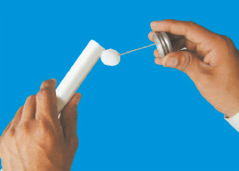
Applicator
- Use an applicator that is one half the pipe diameter.
- Too large an applicator will force excessive cement in to the inside of small diameter fittings. Too small an applicator will not apply sufficient cement to large diameter systems.
Cement
- Apply a full even layer of cement to the outside of a pipe and medium layer of cement to the inside of a fitting.
Join Pipe And Fittings
- Assemble pipe and fitting socket till it contacts socket bottom. Give pipe a quarter turn. Hold pipe and fitting together until the pipe does not back out.
- Remove excessive cement from the exterior. A properly made joint will show a continuous bead of cement around the perimeter.
Carrying Capacity and Friction Loss for Schedule 40 Thermoplastic Pipe
Carrying Capacity and Friction Loss for Schedule 40 Thermoplastic Pipe
(Independent variables : Gallons per minute and nominal pipe size O.D. Dependent variables : Velocity, Friction head and pressure drop per 100 feet of pipe, interior smooth)
| Gallons Per Minute |
Velocity Feet Per Second |
Friction Head Feet |
Friction Loss Pounds / Sq. Inch |
Velocity Feet Per Second |
Friction Head Feet |
Friction Loss Pounds / Sq. Inch |
Velocity Feet Per Second |
Friction Head Feet |
Friction Loss Pounds / Sq. Inch |
Velocity Feet Per Second |
Friction Head Feet |
Friction Loss Pounds / Sq. Inch |
Velocity Feet Per Second |
Friction Head Feet |
Friction Loss Pounds / Sq. Inch |
Velocity Feet Per Second |
Friction Head Feet |
Friction Loss Pounds / Sq. Inch |
Velocity Feet Per Second |
Friction Head Feet |
Friction Loss Pounds / Sq. Inch |
Velocity Feet Per Second |
Friction Head Feet |
Friction Loss Pounds / Sq. Inch |
| |
1½ in. |
¾ in. |
1 in. |
1 ¼ |
1½ in. |
2 in. |
2½ in. |
3 in. |
| 1 |
1.13 |
2.08 |
0.90 |
0.63 |
0.51 |
0.22 |
|
|
|
|
|
|
|
|
|
|
| 2 |
1.26 |
4.16 |
1.80 |
1.26 |
1.02 |
0.44 |
0.77 |
0.55 |
0.24 |
0.44 |
0.14 |
0.06 |
|
|
|
| 5 |
5.64 |
23.44 |
10.15 |
3.16 |
5.73 |
2.48 |
1.93 |
1.72 |
0.75 |
1.11 |
0.44 |
0.19 |
0.33 |
0.07 |
0.03 |
| 7 |
7.90 |
43.06 |
18.64 |
4.43 |
10.52 |
4.56 |
2.72 |
3.17 |
1.37 |
1.55 |
0.81 |
0.35 |
0.81 |
0.22 |
0.09 |
0.49 |
0.066 |
0.029 |
0.30 |
0.038 |
0.016 |
0.22 |
0.015 |
0.007 |
| 10 |
11.28 |
82.02 |
35.51 |
6.32 |
20.04 |
8.68 |
3.86 |
6.02 |
2.61 |
2.21 |
1.55 |
0.67 |
1.13 |
0.38 |
0.17 |
0.69 |
0.11 |
0.048 |
0.49 |
0.051 |
0.023 |
0.31 |
0.021 |
0.009 |
| 15 |
|
4 in. |
|
9.48 |
42.46 |
18.39 |
5.79 |
12.77 |
5.53 |
3.31 |
3.28 |
1.42 |
1.62 |
0.72 |
0.31 |
0.98 |
0.21 |
0.091 |
0.68 |
0.09 |
0.039 |
0.44 |
0.03 |
0.013 |
| 20 |
0.51 |
0.03 |
0.013 |
12.65 |
72.34 |
31.32 |
7.72 |
21.75 |
9.42 |
4.42 |
5.59 |
2.42 |
2.42 |
1.53 |
0.66 |
1.46 |
0.45 |
0.19 |
1.03 |
0.19 |
0.082 |
0.66 |
0.07 |
0.030 |
| 25 |
0.64 |
0.04 |
0.017 |
|
5 in. |
|
9.65 |
32.88 |
14.22 |
5.52 |
8.45 |
3.66 |
3.23 |
2.61 |
1.13 |
1.95 |
0.76 |
0.33 |
1.37 |
0.32 |
0.14 |
0.88 |
0.11 |
0.048 |
| 30 |
0.77 |
0.06 |
0.026 |
0.49 |
0.02 |
0.009 |
11.58 |
46.08 |
19.95 |
6.63 |
11.85 |
5.13 |
4.04 |
3.95 |
1.71 |
2.44 |
1.15 |
0.50 |
1.71 |
0.49 |
0.21 |
1.10 |
0.17 |
0.074 |
| 35 |
0.89 |
0.08 |
0.035 |
0.57 |
0.03 |
0.013 |
|
|
|
7.73 |
15.76 |
6.82 |
4.85 |
5.53 |
2.39 |
2.93 |
1.62 |
0.70 |
2.05 |
0.68 |
0.29 |
1.33 |
0.23 |
0.10 |
| 40 |
1.02 |
0.11 |
0.048 |
0.65 |
0.03 |
0.013 |
|
|
|
8.84 |
20.18 |
8.74 |
5.66 |
7.36 |
3.19 |
3.41 |
2.15 |
0.93 |
2.39 |
0.91 |
0.39 |
1.55 |
0.31 |
0.13 |
| 45 |
1.15 |
0.13 |
0.056 |
0.73 |
0.04 |
0.017 |
|
6 in. |
|
9.94 |
25.10 |
10.87 |
6.47 |
9.43 |
4.08 |
3.90 |
2.75 |
1.19 |
2.73 |
1.16 |
0.50 |
1.77 |
0.40 |
0.17 |
| 50 |
1.28 |
0.16 |
0.069 |
0.81 |
0.05 |
0.022 |
0.56 |
0.02 |
0.009 |
11.05 |
30.51 |
13.21 |
7.27 |
11.73 |
5.08 |
4.39 |
3.43 |
1.49 |
3.08 |
1.44 |
0.62 |
1.99 |
0.50 |
0.22 |
| 60 |
1.53 |
0.22 |
0.095 |
0.97 |
0.07 |
0.030 |
0.67 |
0.03 |
0.013 |
|
|
|
8.08 |
14.25 |
6.17 |
4.88 |
4.16 |
1.80 |
3.42 |
1.75 |
0.76 |
2.21 |
0.60 |
0.26 |
| 70 |
1.79 |
0.30 |
0.13 |
1.14 |
0.10 |
0.043 |
0.79 |
0.04 |
0.017 |
|
|
|
9.70 |
19.98 |
8.65 |
5.85 |
5.84 |
2.53 |
4.10 |
2.46 |
1.07 |
2.65 |
0.85 |
0.37 |
| 75 |
1.92 |
0.34 |
0.15 |
1.22 |
0.11 |
0.048 |
0.84 |
0.05 |
0.022 |
|
|
|
|
|
|
6.63 |
7.76 |
3.36 |
4.79 |
3.27 |
1.42 |
3.09 |
1.13 |
0.49 |
| 80 |
2.05 |
0.38 |
0.16 |
1.30 |
0.13 |
0.056 |
0.90 |
0.05 |
0.022 |
|
|
|
|
|
|
7.32 |
8.82 |
3.82 |
5.13 |
3.71 |
1.61 |
3.31 |
1.28 |
0.55 |
| 90 |
2.30 |
0.47 |
0.20 |
1.46 |
0.16 |
0.069 |
1.01 |
0.06 |
0.026 |
|
|
|
|
|
|
7.80 |
9.94 |
4.30 |
5.47 |
4.19 |
1.81 |
3.53 |
1.44 |
0.62 |
| 100 |
2.56 |
0.58 |
0.25 |
1.62 |
0.19 |
0.082 |
1.12 |
0.08 |
0.035 |
|
8 in. |
|
|
|
|
8.78 |
12.37 |
5.36 |
6.15 |
5.21 |
2.26 |
3.98 |
1.80 |
0.78 |
| 125 |
3.20 |
0.88 |
0.38 |
2.03 |
0.29 |
0.125 |
1.41 |
0.12 |
0.052 |
0.65 |
0.03 |
0.012 |
|
|
|
9.75 |
15.03 |
6.51 |
6.84 |
6.33 |
2.74 |
4.42 |
2.18 |
0.94 |
| 150 |
3.84 |
1.22 |
0.53 |
2.44 |
0.40 |
0.17 |
1.69 |
0.16 |
0.069 |
0.81 |
0.035 |
0.015 |
|
|
|
|
|
|
8.55 |
9.58 |
4.15 |
5.52 |
3.31 |
1.43 |
| 175 |
4.48 |
1.63 |
0.71 |
2.84 |
0.54 |
0.235 |
1.97 |
0.22 |
0.096 |
0.97 |
0.04 |
0.017 |
|
10 in. |
|
|
|
|
10.26 |
13.41 |
5.81 |
6.63 |
4.63 |
2.00 |
| 200 |
5.11 |
2.08 |
0.90 |
3.25 |
0.69 |
0.30 |
2.25 |
0.28 |
0.12 |
1.14 |
0.055 |
0.024 |
|
|
|
|
|
|
|
|
|
7.73 |
6.16 |
2.67 |
| 250 |
6.40 |
3.15 |
1.36 |
4.06 |
1.05 |
0.45 |
2.81 |
0.43 |
0.19 |
1.30 |
0.07 |
0.030 |
1.03 |
0.035 |
0.015 |
|
|
|
|
|
|
8.83 |
7.88 |
3.41 |
| 300 |
7.67 |
4.41 |
1.91 |
4.87 |
1.46 |
0.63 |
3.37 |
0.60 |
0.26 |
1.63 |
0.11 |
0.048 |
1.23 |
0.05 |
0.022 |
|
12 in. |
|
|
|
|
11.04 |
11.93 |
5.17 |
| 350 |
8.95 |
5.87 |
2.55 |
5.69 |
1.95 |
0.85 |
3.94 |
0.79 |
0.34 |
1.94 |
0.16 |
0.069 |
1.44 |
0.065 |
0.028 |
|
|
|
|
|
|
|
|
|
| 400 |
10.23 |
7.52 |
3.26 |
6.50 |
2.49 |
1.08 |
4.49 |
1.01 |
0.44 |
2.27 |
0.21 |
0.091 |
1.64 |
0.09 |
0.039 |
1.16 |
0.04 |
0.017 |
|
|
|
|
|
|
| 450 |
|
|
|
7.31 |
3.09 |
1.34 |
5.06 |
1.26 |
0.55 |
2.59 |
0.27 |
0.12 |
1.85 |
0.11 |
0.048 |
1.30 |
0.05 |
0.022 |
|
|
|
|
|
|
| 500 |
|
|
|
8.12 |
3.76 |
1.63 |
5.62 |
1.53 |
0.66 |
2.92 |
0.33 |
0.14 |
2.05 |
0.13 |
0.056 |
1.45 |
0.06 |
0.026 |
|
|
|
|
|
|
| 750 |
|
|
|
|
|
|
8.43 |
3.25 |
1.41 |
3.24 |
0.40 |
0.17 |
3.08 |
0.28 |
0.12 |
2.17 |
0.12 |
0.052 |
|
|
|
|
|
|
| 1000 |
|
|
|
|
|
|
11.24 |
5.54 |
2.40 |
4.86 |
0.85 |
0.37 |
4.11 |
0.48 |
0.21 |
2.89 |
0.20 |
0.087 |
|
|
|
|
|
|
| 1250 |
|
|
|
|
|
|
|
|
|
6.48 |
1.45 |
0.63 |
5.14 |
0.73 |
0.32 |
3.62 |
0.31 |
0.13 |
|
|
|
|
|
|
| 1500 |
|
|
|
|
|
|
|
|
|
8.11 |
2.20 |
0.95 |
6.16 |
1.01 |
0.44 |
4.34 |
0.43 |
0.19 |
|
|
|
|
|
|
| 2000 |
|
|
|
|
|
|
|
|
|
9.72 |
3.07 |
1.33 |
8.21 |
1.72 |
0.74 |
5.78 |
0.73 |
0.32 |
|
|
|
|
|
|
| 2500 |
|
|
|
|
|
|
|
|
|
|
|
|
10.27 |
2.61 |
1.13 |
7.23 |
1.11 |
0.49 |
|
|
|
|
|
|
| 3000 |
|
|
|
|
|
|
|
|
|
|
|
|
|
|
|
8.68 |
1.55 |
0.67 |
|
|
|
|
|
|
| 3500 |
|
|
|
|
|
|
|
|
|
|
|
|
|
|
|
10.12 |
2.07 |
0.90 |
|
|
|
|
|
|
Carrying Capacity and Friction Loss for Schedule 80 Thermoplastic Pipe
(Independent variables : Gallons per minute and nominal pipe size O.D. Dependent variables : Velocity, Friction head and pressure drop per 100 feet of pipe, interior smooth)
| Gallons Per Minute |
Velocity Feet Per Second |
Friction Head Feet |
Friction Loss Pounds / Sq. Inch |
Velocity Feet Per Second |
Friction Head Feet |
Friction Loss Pounds / Sq. Inch |
Velocity Feet Per Second |
Friction Head Feet |
Friction Loss Pounds / Sq. Inch |
Velocity Feet Per Second |
Friction Head Feet |
Friction Loss Pounds / Sq. Inch |
Velocity Feet Per Second |
Friction Head Feet |
Friction Loss Pounds / Sq. Inch |
Velocity Feet Per Second |
Friction Head Feet |
Friction Loss Pounds / Sq. Inch |
Velocity Feet Per Second |
Friction Head Feet |
Friction Loss Pounds / Sq. Inch |
Velocity Feet Per Second |
Friction Head Feet |
Friction Loss Pounds / Sq. Inch |
| |
1½ in. |
¾ in. |
1 in. |
1 ¼ |
1½ in. |
2 in. |
2½ in. |
3 in. |
| 1 |
1.48 |
4.02 |
1.74 |
0.74 |
0.86 |
0.37 |
|
|
|
|
|
|
|
|
|
|
| 2 |
2.95 |
8.03 |
3.48 |
1.57 |
1.72 |
0.74 |
0.94 |
0.88 |
0.38 |
0.52 |
0.21 |
0.09 |
|
|
|
| 5 |
7.39 |
45.23 |
19.59 |
3.92 |
9.67 |
4.19 |
2.34 |
2.75 |
1.19 |
1.30 |
0.66 |
0.29 |
0.38 |
0.10 |
0.041 |
| 7 |
10.34 |
83.07 |
35.97 |
5.49 |
17.76 |
7.69 |
3.28 |
5.04 |
2.19 |
1.82 |
1.21 |
0.53 |
0.94 |
0.30 |
0.126 |
0.56 |
0.10 |
0.040 |
0.39 |
0.05 |
0.022 |
0.25 |
0.02 |
0.009 |
| 10 |
|
|
|
7.84 |
33.84 |
14.65 |
4.68 |
9.61 |
4.16 |
2.60 |
2.30 |
1.00 |
1.32 |
0.55 |
0.24 |
0.78 |
0.15 |
0.065 |
0.54 |
0.07 |
0.032 |
0.35 |
0.028 |
0.012 |
| 15 |
|
4 in. |
|
11.76 |
71.70 |
31.05 |
7.01 |
20.36 |
8.82 |
3.90 |
4.87 |
2.11 |
1.88 |
1.04 |
0.45 |
1.12 |
0.29 |
0.13 |
0.78 |
0.12 |
0.052 |
0.50 |
0.04 |
0.017 |
| 20 |
0.57 |
0.04 |
0.017 |
|
|
|
9.35 |
34.68 |
15.02 |
5.20 |
8.30 |
3.59 |
2.81 |
2.20 |
0.95 |
1.68 |
0.62 |
0.27 |
1.17 |
0.26 |
0.11 |
0.75 |
0.09 |
0.039 |
| 25 |
0.72 |
0.06 |
0.026 |
|
5 in. |
|
11.69 |
52.43 |
22.70 |
6.50 |
12.55 |
5.43 |
3.75 |
3.75 |
1.62 |
2.23 |
1.06 |
0.46 |
1.56 |
0.44 |
0.19 |
1.00 |
0.15 |
0.065 |
| 30 |
0.86 |
0.08 |
0.035 |
0.54 |
0.03 |
0.013 |
14.03 |
73.48 |
31.82 |
7.80 |
17.59 |
7.62 |
4.69 |
5.67 |
2.46 |
2.79 |
1.60 |
0.69 |
1.95 |
0.67 |
0.29 |
1.25 |
0.22 |
0.095 |
| 35 |
1.00 |
0.11 |
0.048 |
0.63 |
0.04 |
0.017 |
|
|
|
9.10 |
23.40 |
10.13 |
5.63 |
7.95 |
3.44 |
3.35 |
2.25 |
0.97 |
2.34 |
0.94 |
0.41 |
1.49 |
0.31 |
0.13 |
| 40 |
1.15 |
0.14 |
0.061 |
0.72 |
0.04 |
0.017 |
|
|
|
10.40 |
29.97 |
12.98 |
6.57 |
10.58 |
4.58 |
3.91 |
2.99 |
1.29 |
2.73 |
1.25 |
0.54 |
1.74 |
0.42 |
0.18 |
| 45 |
1.29 |
0.17 |
0.074 |
0.81 |
0.06 |
0.026 |
|
6 in. |
|
11.70 |
37.27 |
16.14 |
7.50 |
13.55 |
5.87 |
4.47 |
3.83 |
1.66 |
3.12 |
1.60 |
0.69 |
1.99 |
0.54 |
0.23 |
| 50 |
1.43 |
0.21 |
0.091 |
0.90 |
0.07 |
0.030 |
0.63 |
0.03 |
0.013 |
13.00 |
45.30 |
19.61 |
8.44 |
16.85 |
7.30 |
5.03 |
4.76 |
2.07 |
3.51 |
1.99 |
0.86 |
2.24 |
0.67 |
0.29 |
| 60 |
1.72 |
0.30 |
0.13 |
1.08 |
0.10 |
0.043 |
0.75 |
0.04 |
0.017 |
|
|
|
9.38 |
20.48 |
8.87 |
5.58 |
5.79 |
2.51 |
3.90 |
2.42 |
1.05 |
2.49 |
0.81 |
0.35 |
| 70 |
2.01 |
0.39 |
0.17 |
1.26 |
0.13 |
0.056 |
0.88 |
0.05 |
0.022 |
|
|
|
11.26 |
28.70 |
12.43 |
6.70 |
8.12 |
3.52 |
4.68 |
3.39 |
1.47 |
2.99 |
1.14 |
0.49 |
| 75 |
2.15 |
0.45 |
0.19 |
1.35 |
0.14 |
0.061 |
0.94 |
0.06 |
0.026 |
|
|
|
|
|
|
7.82 |
10.80 |
4.68 |
5.46 |
4.51 |
1.95 |
3.49 |
1.51 |
0.65 |
| 80 |
2.29 |
0.50 |
0.22 |
1.44 |
0.16 |
0.069 |
1.00 |
0.07 |
0.030 |
|
|
|
|
|
|
8.38 |
12.27 |
5.31 |
5.85 |
5.12 |
2.22 |
3.74 |
1.72 |
0.74 |
| 90 |
2.58 |
0.63 |
0.27 |
1.62 |
0.20 |
0.087 |
1.13 |
0.08 |
0.035 |
|
|
|
|
|
|
8.93 |
13.83 |
5.99 |
6.24 |
5.77 |
2.50 |
3.99 |
1.94 |
0.84 |
| 100 |
2.87 |
0.76 |
0.33 |
1.80 |
0.24 |
0.10 |
1.25 |
0.10 |
0.043 |
|
8 in. |
|
|
|
|
10.05 |
17.20 |
7.45 |
7.02 |
7.18 |
3.11 |
4.48 |
2.41 |
1.04 |
| 125 |
3.59 |
1.16 |
0.50 |
2.25 |
0.37 |
0.16 |
1.57 |
0.16 |
0.068 |
0.90 |
0.045 |
0.019 |
|
|
|
11.17 |
20.90 |
9.05 |
7.80 |
8.72 |
3.78 |
4.98 |
2.93 |
1.27 |
| 150 |
4.30 |
1.61 |
0.70 |
2.70 |
0.52 |
0.23 |
1.88 |
0.22 |
0.095 |
1.07 |
0.05 |
0.022 |
|
|
|
|
|
|
9.75 |
13.21 |
5.72 |
6.23 |
4.43 |
1.92 |
| 175 |
5.2 |
2.15 |
0.93 |
3.15 |
0.69 |
0.30 |
2.20 |
0.29 |
0.12 |
1.25 |
0.075 |
0.033 |
|
10 in. |
|
|
|
|
11.70 |
18.48 |
8.00 |
7.47 |
6.20 |
2.68 |
| 200 |
5.73 |
2.75 |
1.19 |
3.60 |
0.88 |
0.38 |
2.51 |
0.37 |
0.16 |
1.43 |
0.09 |
0.039 |
|
|
|
|
|
|
|
|
|
8.72 |
8.26 |
3.58 |
| 250 |
7.16 |
4.16 |
1.81 |
4.50 |
1.34 |
0.58 |
3.14 |
0.56 |
0.24 |
1.79 |
0.14 |
0.61 |
1.14 |
0.045 |
0.02 |
|
|
|
|
|
|
9.97 |
10.57 |
4.58 |
| 300 |
8.60 |
5.83 |
2.52 |
5.40 |
1.87 |
0.81 |
3.76 |
0.78 |
0.34 |
2.14 |
0.20 |
0.087 |
1.36 |
0.07 |
0.03 |
|
12 in. |
|
|
|
|
12.46 |
16.00 |
6.93 |
| 350 |
10.03 |
7.76 |
3.36 |
6.30 |
2.49 |
1.08 |
4.39 |
1.04 |
0.45 |
2.50 |
0.27 |
0.12 |
1.59 |
0.085 |
0.037 |
|
|
|
|
|
|
|
|
|
| 400 |
11.47 |
9.93 |
4.30 |
7.19 |
3.19 |
1.38 |
5.02 |
1.33 |
0.58 |
2.86 |
0.34 |
0.15 |
1.81 |
0.11 |
0.048 |
1.28 |
0.05 |
0.022 |
|
|
|
|
|
|
| 450 |
|
|
|
8.09 |
3.97 |
1.72 |
5.64 |
1.65 |
0.71 |
3.21 |
0.42 |
0.18 |
2.04 |
0.14 |
0.061 |
1.44 |
0.06 |
0.026 |
|
|
|
|
|
|
| 500 |
|
|
|
8.99 |
4.82 |
2.09 |
6.27 |
2.00 |
0.87 |
3.57 |
0.51 |
0.22 |
2.27 |
0.17 |
0.074 |
1.60 |
0.07 |
0.030 |
|
|
|
|
|
|
| 750 |
|
|
|
|
|
|
9.40 |
4.25 |
1.84 |
5.36 |
1.08 |
0.47 |
3.40 |
0.36 |
0.16 |
2.40 |
0.15 |
0.065 |
|
|
|
|
|
|
| 1000 |
|
|
|
|
|
|
12.54 |
7.23 |
3.13 |
7.14 |
1.84 |
0.80 |
4.54 |
0.61 |
0.26 |
3.20 |
0.26 |
0.11 |
|
|
|
|
|
|
| 1250 |
|
|
|
|
|
|
|
|
|
8.93 |
2.78 |
1.20 |
5.67 |
0.92 |
0.40 |
4.01 |
0.40 |
0.17 |
|
|
|
|
|
|
| 1500 |
|
|
|
|
|
|
|
|
|
10.71 |
3.98 |
1.68 |
6.80 |
1.29 |
0.56 |
4.81 |
0.55 |
0.24 |
|
|
|
|
|
|
| 2000 |
|
|
|
|
|
|
|
|
|
|
|
|
9.07 |
2.19 |
0.95 |
6.41 |
0.94 |
0.41 |
|
|
|
|
|
|
| 2500 |
|
|
|
|
|
|
|
|
|
|
|
|
11.34 |
3.33 |
1.44 |
8.01 |
1.42 |
0.62 |
|
|
|
|
|
|
| 3000 |
|
|
|
|
|
|
|
|
|
|
|
|
|
|
|
9.61 |
1.99 |
0.86 |
|
|
|
|
|
|
| 3500 |
|
|
|
|
|
|
|
|
|
|
|
|
|
|
|
11.21 |
2.65 |
1.15 |
|
|
|
|
|
|
Read Less