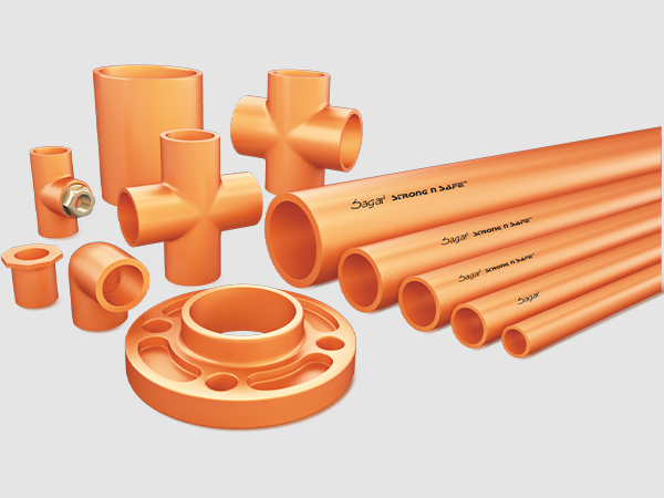
Fire Sprinkler Systems
Sprinkler Head Temperature Ratings:
FireMan pipe and fittings shall be used in sprinkler systems employing sprinkler heads rated 225°F (107°C) or lower, for pendent and horizontal sidewall heads. Quick-Response upright heads shall be rated of 155°F (68°C) or less.
Pipe :
CPVC Sprinkler pipe in SDR 13.5 conforms to the requirements of ASTM F442.
Fittings
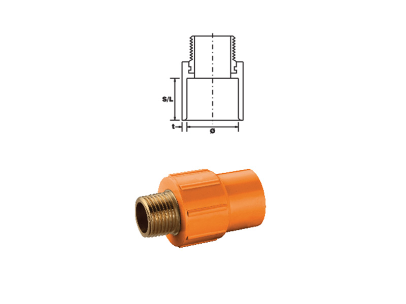
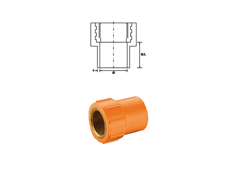
FireMan CPVC Sprinkler fittings conform to the requirement of ASTM F 438 (Schedule 40) & ASTM F439 (Schedule 80). Female threaded adapters for sprinkler head connections will contain brass inserts or other suitable metallic inserts.
Solvent Cement:
FireMan CPVC socket connections should be joined with IPS weld on solvent cement which meets ASTM F493. No other cements are recommended for use with FireMan products and use of such non-proved welding agents will invalidate the manufacturers warranty.
Full field support:
FireMan CPVC systems are backed by an extensive field support organization providing:
- Proven installation recommendations to maximize efficiency and cost savings
- Compliance advice for local, regional and national building codes
- Expert design and specification recommendations With a high flash ignition temperature, low flame spread and smoke development ratings, and a fuel contribution of 0, FireMan pipe and fittings are an ideal choice for fire sprinkler systems
FireMan pipe and fittings meet the most stringent requirements governing the use of\ combustible pipe in most building types. FireMan pipe and fittings have been successfully exposed to flame temperatures of 1400°F. After undergoing continuous elevated pressure testing at 400 psi (more than twice the rated pressure) for more than one year, FireMan CPVC systems showed no sign of weakness or failure.
FireMan pipe and fittings are manufactured under a strict Quality Assurance Program that guarantees consistency and reliability. Pipe and fittings are impervious to normal weather conditions and are fundamentally ageless.
FireMan CPVC systems for designers, architects and engineers:
FireMan pipe and fittings offer greatly enhanced design flexibility. With a Hazen-Williams C factor of 150, its smooth inner surface results in lower friction loss than metal systems. This means you can use smaller pipe diameters which lowers your material costs and provides additional design flexibility in retrofit applications. FireMan pipe and fittings have a 50-year life expectancy with a safety factor of two. Properly selected and correctly installed, FireMan pipe and fittings provide years of maintenance free service.
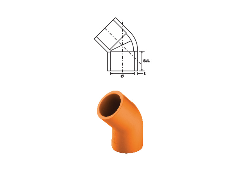
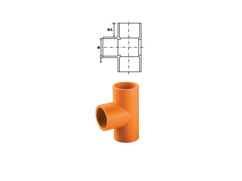
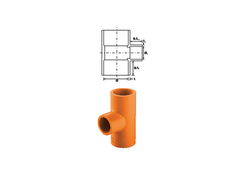
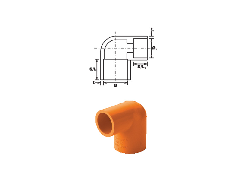
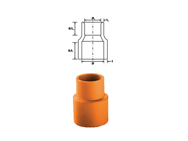
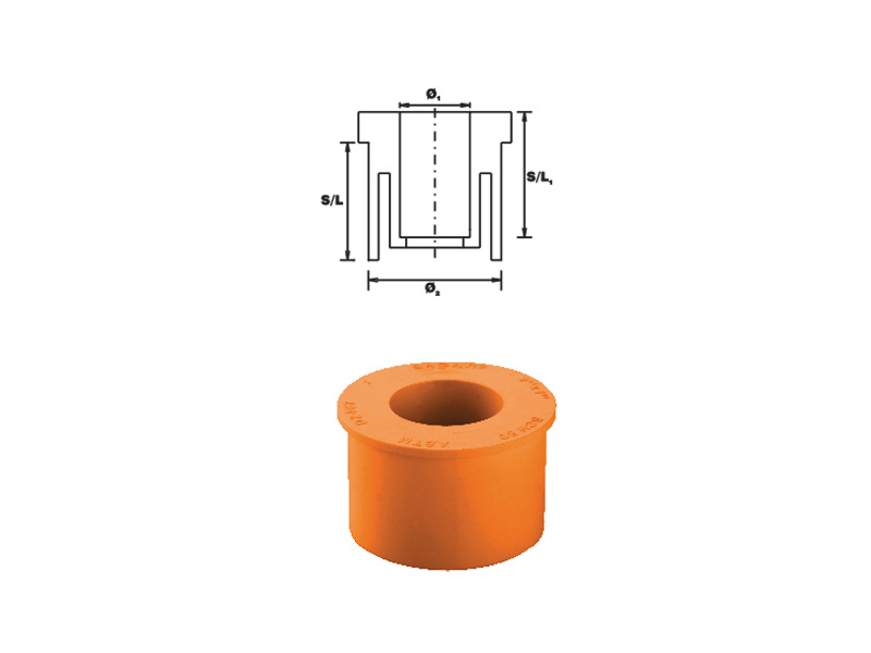
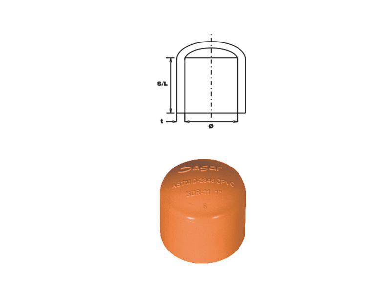
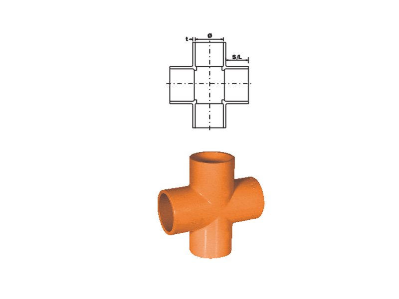
Fire Sprinkler Fittings Specifications
SAGAR Sprinkler Fittings Technical Specifications:
| Size (Inch) |
Thickness
' t '
(Min.) |
Thickness
' t1 '
(Min.) |
Thickness
' t2 '
(Min.) |
Socket Length
'S/L'
(Min.) |
Socket Length
'S/L1'
(Min.) |
Socket
I.D.
'Ø ' |
Socket
I.D.
'Ø1 ' |
R. Bushing
O.D.
'Ø2 ' |
| Min. |
Max. |
Min. |
Max. |
Min. |
Max. |
| ¾ x ½ |
0.113 |
0.109 |
0.136 |
0.719 |
0.688 |
1.042 |
1.062 |
0.832 |
0.852 |
1.046 |
1.057 |
| 1 x ½ |
0.133 |
0.109 |
0.136 |
0.875 |
0.688 |
1.305 |
1.330 |
0.832 |
0.852 |
1.310 |
1.323 |
| 1 x ¾ |
0.133 |
0.113 |
0.141 |
0.875 |
0.719 |
1.305 |
1.330 |
1.042 |
1.062 |
1.310 |
1.323 |
| 1¼ x ½ |
0.140 |
0.109 |
0.136 |
0.938 |
0.688 |
1.650 |
1.675 |
0.832 |
0.852 |
1.655 |
1.668 |
| 1¼ x ¾ |
0.140 |
0.133 |
0.141 |
0.938 |
0.719 |
1.650 |
1.675 |
1.042 |
1.062 |
1.655 |
1.668 |
| 1¼ x 1 |
0.140 |
0.133 |
0.166 |
0.938 |
0.875 |
1.650 |
1.675 |
1.305 |
1.330 |
1.655 |
1.668 |
| 1½ x ½ |
0.145 |
0.109 |
0.136 |
1.094 |
0.688 |
1.888 |
1.918 |
0.832 |
0.852 |
1.894 |
1.910 |
| 1½ x ¾ |
0.145 |
0.113 |
0.141 |
1.094 |
0.719 |
1.888 |
1.918 |
1.042 |
1.062 |
1.894 |
1.910 |
| 1½ x 1 |
0.145 |
0.133 |
0.166 |
1.094 |
0.875 |
1.888 |
1.918 |
1.305 |
1.330 |
1.894 |
1.910 |
| 1½ x 1¼ |
0.145 |
0.140 |
0.175 |
1.094 |
0.938 |
1.888 |
1.918 |
1.650 |
1.675 |
1.894 |
1.910 |
| 2 x ½ |
0.154 |
0.109 |
0.136 |
1.156 |
0.688 |
2.363 |
2.393 |
0.832 |
0.852 |
2.369 |
2.385 |
| 2 x ¾ |
0.154 |
0.113 |
0.141 |
1.156 |
0.719 |
2.363 |
2.393 |
1.042 |
1.062 |
2.369 |
2.385 |
| 2 x 1 |
0.154 |
0.133 |
0.166 |
1.156 |
0.875 |
2.363 |
2.393 |
1.305 |
1.330 |
2.369 |
2.385 |
| 2 x 1¼ |
0.154 |
0.140 |
0.175 |
1.156 |
0.938 |
2.363 |
2.393 |
1.650 |
1.675 |
2.369 |
2.385 |
| 2 x 1½ |
0.154 |
0.145 |
0.181 |
1.156 |
1.094 |
2.363 |
2.393 |
1.888 |
1.918 |
2.369 |
2.385 |
| 2½ x 2 |
0.203 |
0.154 |
0.193 |
1.750 |
1.156 |
2.861 |
2.896 |
2.363 |
2.393 |
2.868 |
2.887 |
| 3 x 1½ |
0.216 |
0.145 |
0.181 |
1.875 |
1.094 |
3.484 |
3.524 |
1.888 |
1.918 |
3.492 |
3.513 |
| 3 x 2 |
0.216 |
0.154 |
0.193 |
1.875 |
1.156 |
3.484 |
3.524 |
2.363 |
2.393 |
3.492 |
3.513 |
| 3 x 2½ |
0.216 |
0.203 |
0.254 |
1.875 |
1.750 |
3.484 |
3.524 |
2.861 |
2.896 |
3.492 |
3.513 |
| 4 x 2 |
0.237 |
0.154 |
0.193 |
2.000 |
1.156 |
4.482 |
4.527 |
2.363 |
2.393 |
4.491 |
4.515 |
| 4 x 2½ |
0.237 |
0.203 |
0.254 |
2.000 |
1.750 |
4.482 |
4.527 |
2.861 |
2.896 |
4.491 |
4.515 |
| 4 x 3 |
0.237 |
0.216 |
0.270 |
2.000 |
1.875 |
4.482 |
4.527 |
3.484 |
3.524 |
4.491 |
4.515 |
| 6 x 3 |
0.280 |
0.216 |
0.270 |
3.000 |
1.875 |
6.603 |
6.658 |
3.484 |
3.524 |
6.614 |
6.643 |
| 6 x 4 |
0.280 |
0.237 |
0.296 |
3.000 |
2.000 |
6.603 |
6.658 |
4.482 |
4.527 |
6.614 |
6.643 |
Note:
- All Dimensions are in inch.
- 1 inch = 25.4 mm.
- Please contact at your nearest place for available size for particular type of fitting.
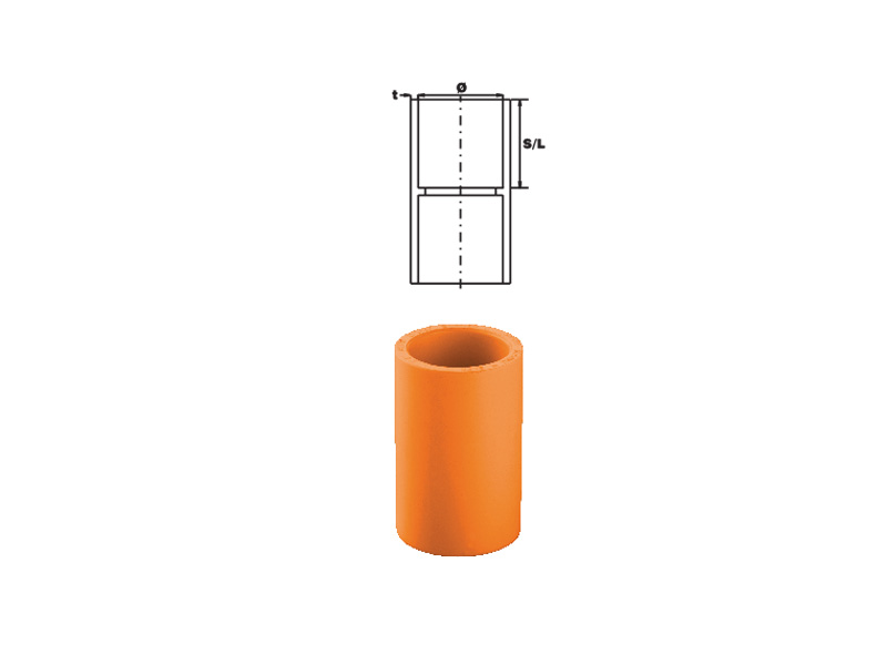
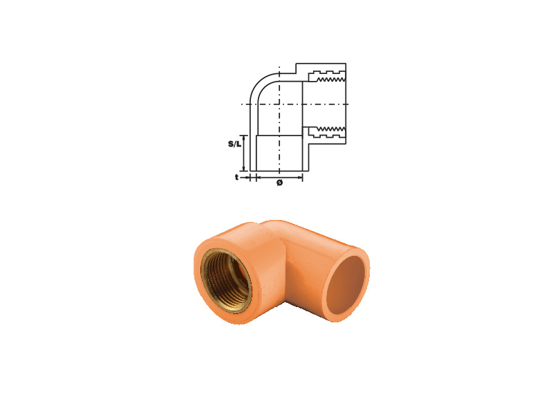
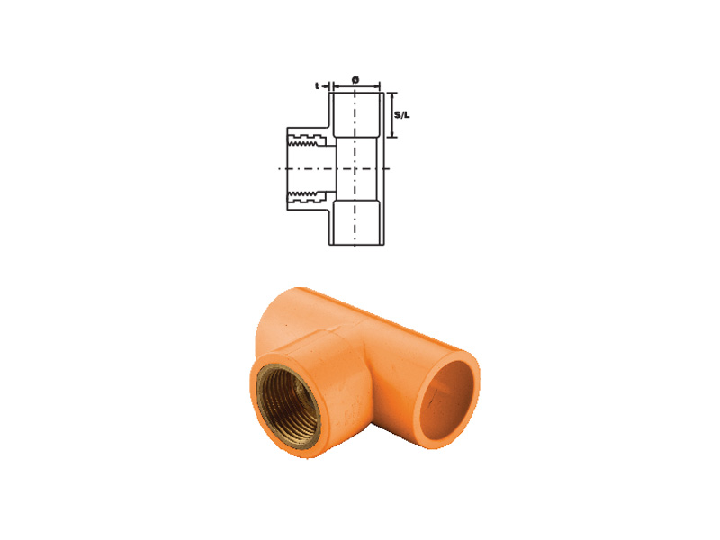
Technical Specifications of Fittings
| Size (Inch) |
Thickness
' t '
(Min.) |
Socket Length
'S/L'
(Min.) |
Socket
I.D.
'Ø ' |
Thread (TPI) |
| Min. |
Max. |
| ½ |
0.109 |
0.688 |
0.832 |
0.852 |
14 |
| ¾ |
0.113 |
0.719 |
1.042 |
1.062 |
14 |
| 1 |
0.133 |
0.875 |
1.305 |
1.330 |
11 |
| 1¼ |
0.140 |
0.938 |
1.650 |
1.675 |
11 |
| 1½ |
0.145 |
1.094 |
1.888 |
1.918 |
11 |
| 2 |
0.154 |
1.156 |
2.363 |
2.393 |
11 |
| 2½ |
0.203 |
1.750 |
2.861 |
2.896 |
11 |
| 3 |
0.216 |
1.875 |
3.484 |
3.524 |
11 |
| 4 |
0.237 |
2.000 |
4.482 |
4.527 |
11 |
| 6 |
0.280 |
3.000 |
6.603 |
6.658 |
11 |
Note:
- All Dimensions are in inch.
- 1 inch = 25.4 mm.
- Please contact at your nearest place for available size for particular type of fitting.
Other Differentiation
- • Sizes available up to 3"
- • Approved commercial product for over 20 years
- • Backed by over 40 years of CPVC resin and compound manufacturing experience
- • CPVC resin & compound from ISO 9001 manufacturing facilities
- • System chemical compatibility program (ancillary products) backed by independent thrid party testing/verification
- • Formal installation training program which has more than 10,000 graduates
- • Developed UL approved cut-in procedure
- • Leader in new Listing and Approved developments
- • Dedicated CPVC system field consultants
- • CPVC pipe compound pressure rated by Plastics Pipe Institute
- • CPVC fitting compound pressure rated by Plastics Pipe Institute
- • Pipe compound cell class, 23547, exceeds the minimum allowable ASTM requirements for CPVC tensile strength
- • Fitting compound cell class, 24447, exceeds the minimum allowable ASTM requirements for CPVC impact strength
Fire Sprinkler Systems
FireMan CPVC systems for builders and developers:
FireMan pipe and fittings significantly reduce labor and transportation costs on typical installations because CPVC pipe is easily handled, stored, cut and joined. Prices for FireMan CPVC pipe and fittings are more stable than metal systems. Plus, heavy equipment needed to install metal and other piping systems is not required with FireMan pipe and fittings. As a result, installed costs of FireMan CPVC systems are significantly lower than metal and other systems.
The inherent immunity to Micro biologically Influenced Corrosion (MIC) of FireMan pipe and fittings means this system provides a long-term trouble-free installation. As well, there is significantly less inconvenience for occupants during retrofit construction.
FireMan CPVC systems for contractors:
Installation of FireMan pipe and fittings is fast and easy. No special rigging or heavy equipment is required to move the pipe into a building. Pipe can be cut on-site with simple hand tools. A one-step joining system makes installations fast, keeping labor costs to a minimum.
Because no heavy equipment is involved in moving and installing pipe and fittings on-site, there is less conflict with other trades. Work can be done quickly and easily around drywallers, framers and other mechanical contractors.
Most hangers designed for metal pipe are suitable for FireMan CPVC systems. Because FireMan pipe is rigid and inherently strong, it requires fewer hangars and supports than other thermoplastic pipe, reducing material and labor costs even more.
The ideal solution for the sprinkler systems:
FireMan pipe and fittings are ideal for wet automatic fire sprinkler systems with an outstanding combination of features including:
- • Easy assembly
- • Light weight construction
- • Low friction loss
- • No rusting, pitting, scaling or corrosion, even in salt air environments
- • Immunity to Micro biologically Influenced Corrosion (MIC)
FireMan pipe and fittings have been successfully exposed to temperatures of 1400°F (760°C), and after continuous elevated pressure testing at 400 psi, (more than twice the rated pressure) FireMan showed no sign of weakness or failure. With a Hazen-Williams friction coefficient of C=150, FireMan's smooth interior surface offers lower friction loss than metal systems, enables to use smaller pipe diameters and save on material costs.
Fire Sprinkler Systems
Flammability:
FireMan CPVC is ideally suited for wet automatic fire sprinkler systems due to its out standing balance of properties such as light weight, excellent corrosion resistance, low friction loss and ease of fabrication. FireMan CPVC is unique in that it offers outstanding resistance to fire and low smoke generation qualities. Because of these features, FireMan systems are approved for use in plenum spaces as defined by NFPA 90A, the National Standard for the Installation of Air Conditioning and Ventilating Systems.
Ignition Resistance:
FireMan CPVC has a flash ignition temperature of 900°F which is the lowest temperature at which sufficient combustible gas is evolved that can be ignited by a small external flame. Many other ordinary combustibles, such as wood, ignite at 500°F or less. Accordingly, FireMan systems cannot be the ignition source of a fire.
Burning Resistance:
FireMan CPVC will not sustain burning. It must be forced to burn due to its very high Limiting Oxygen Index (LOI) of 60. LOI is the percentage of oxygen needed in an atmosphere to support combustion. Since earth’s atmosphere is only 21% oxygen, FireMan CPVC will not burn unless a flame is constantly applied and stops burning when the ignition source is removed.
Low Frication Loss:
With a Hazen-Williams friction coefficient of C=150, ® FireMan ’s smooth interior surface offers lower friction loss than metal systems, enables to use smaller pipe diameters and save on material costs.
Lower Installation Cost:
Lightweight and easy to handle, store, to cut and join, ® FireMan also offers lower installation costs than metal systems. No special rigging or heavy equipment is required. Rigid and inherent ly st rong, ® FireMan uses standard metal pipe hangers and requires fewer hangers and supports than other thermoplastic pipe, further reducing material and labor costs.
Heat of Combustion:
® FireMan CPVC has a significantly lower heat of combustion at 7,700 BTU’s/lb, compared to Douglas fir at 9,040 BTU’s/lb, and polypropylene at nearly 20,000 BTU’s/lb. Materials with a high heat of combustion perpetuate a combust ible mixture which igni tes creating more heat and the burning process becomes selfsustaining.
Temperature / Pressure Rating:
® FireMan pipe and fittings (¾" - 3" (20 - 80 mm) are rated for continuous service of 175 psi (1207 KPa) at 150°F ® (65°C). FireMan pipe and fittings are suitable for use in areas where ambient temperatures are within the range of 35°F (2°C) to 150° F (66°C).
Flame Spread / Smoke Generation:
The flame spread and smoke generation characteristics of FireMan CPVC materials have been evaluated by Underwriters Laboratories of Canada (ULC), Underwriters Laboratories, Inc. (ULI) and the Southwest Research Institute (SWRI) employing a number of recognized test methodologies. The ULC method, CAN-S102.2M83 compares the flame spread, smoke development and fuel contribution of a material to a known “non-combustible” and a known “combustible” on a scale of 0 – 100, respectively, as follows:
Fire Sprinkler Systems
| |
Classification or Rating |
| Flame |
Smoke |
Fuel |
| Material |
Spread |
Developed |
Contribution |
| 0.8 to 1.6 MM thick |
0 |
0.25 |
0 |
System Benefits:
- • No precutting and expensive fabrication required.
- • Easily connected to other sprinkler piping systems
- • Flexibility in the piping for greater ease of installation.
- • Resistant to rust, scale and foreign contaminant build up.
- • Inexpensive tools required for installation
- • Easily repaired or modified on site.
- • Designed to a 50 year life expectancy.
Basic Principles of Solvent Cementing:
The solvent cemented connection in thermoplastic pipe and fittings is the last vital link in a plastic pipe installation. It can mean the success or failure of thesystem as a whole. Accordingly, it requires the same professional care and attention that are given to other components of the system.
There are many solvent cementing techniques published covering step by step procedures on just how to make solvent cemented joints. However, we feel that if the basic principles involved are explained, known and understood, a better understanding would be gained, as to what techniques are necessary to suit particular applications, temperature conditions, and variations in size and fits of pipe and fittings.
Be aware at all times of good safety practices. Solvent cements for pipe and fittings are flammable, so there should be no smoking nor other sources of heat or flame in working or storage areas. Be sure to work only in a well ventilated space and avoid unnecessary skin contact with all solvents. More detailed safety information is available from Harvel or IPS (Weld-On) Corporation.
To consistently make good joints, the following should be carefully understood:
- • The joining surfaces must be softened and made semifluid.
- • Sufficient cement must be applied to fill the gap between pipe and fitting.
- • Assembly of pipe and fittings must be made while the surfaces are still wet and fluid.
- • Joint strength develops as the cement dries. In the tight part of the joint the surfaces will tend to fuse together, in the loose part the cement will bond to both surfaces.
The change in length caused by thermal expansion or contraction can be calculated as follows:
- ΔL = 12 eL (T)
- e = 3.4 x 10⁻⁵ in./in. °F (Coefficient of Linear Expansion – Table II.)
- L = Length of Run in Feet
- ΔT = Temperature Change in °F (difference between lowest system temperature and maximum system temperature – whichever is greatest)
- Example: How much will a 40 ft. run of 2" GF Harvel CPVC Fire Sprinkler pipe expand if the expected ambient temperature will range from 45° to 85°FΔ
- ΔL = 12 eL (T)
- ΔL = 12 (.000034) x 40 x 40
- ΔL = .65”
The change in length (L) in inches based on temperature change and length of run is shown in Table
| Modulus of Elasticity & Stress vs. Temperature |
| Temperature °F |
73° |
80° |
90° |
100° |
110° |
120° |
140° |
150° |
| Modulus of Elasticity “E” x 105 psi |
4.23 |
4.14 |
3.99 |
3.85 |
3.70 |
3.55 |
3.23 |
3.08 |
| Working Stress “S” psi |
2,000 |
1,875 |
1,715 |
1,560 |
1,415 |
1,275 |
1,000 |
875 |
Table II
| Physical & Thermal Properties |
| Property |
|
CPVC |
ASTM |
| Specific Gravity |
“Sp. Gr.” |
1.55 |
D 792 |
| IZOD Impact Strength (ft. lbs./inch of notch) |
- |
3.0 |
D 256A |
| Modulus of Elasticity, psi |
“E” |
4.23 x 10⁵ |
D 638 |
| Ultimate Tensile Strength, psi |
- |
8,400 |
D 638 |
| Compressive Strength, psi |
“s” |
9,600 |
D 695 |
| Poisson's Ratio |
“n” |
.35-.38 |
- |
| Working Stress @ 73°F, psi |
“S” |
2,000 |
D 1598 |
| Hazen-Williams “C”Factor |
“e” |
150 |
- |
| Coefficient of Linear Expansion in./(in. °F) |
“k” |
3.4 x 10⁻⁵ |
D 696 |
| Thermal Conductivity BTU in/hr/ft2/°F |
“°f” |
0.95 |
C 177 |
| Upper Temperature Limit |
|
210 |
- |
| Flammability |
Flame Retardant |
| Electrical Conductivity |
Non Conductor |
| Thermal Expansion in inches |
| Temp.Change ATF |
Length of Run in Feet |
| 5 |
10 |
15 |
20 |
25 |
30 |
35 |
40 |
45 |
50 |
70 |
90 |
120 |
160 |
| Thermal Expansion AL ( In .) |
| 20 |
.04 |
.08 |
.12 |
.16 |
.20 |
.24 |
.29 |
.33 |
.37 |
.41 |
.57 |
.73 |
.98 |
1.31 |
| 30 |
.06 |
.12 |
.24 |
.24 |
.31 |
.37 |
.43 |
.49 |
.55 |
.61 |
.86 |
1.10 |
1.47 |
1.96 |
| 40 |
.08 |
.16 |
.33 |
.41 |
.41 |
.49 |
.57 |
.65 |
.74 |
.82 |
1.14 |
1.47 |
1.96 |
2.61 |
| 50 |
.10 |
.20 |
.41 |
.51 |
.51 |
.61 |
.72 |
.82 |
.92 |
1.02 |
1.43 |
1.84 |
2.45 |
3.26 |
| 60 |
.12 |
.24 |
.49 |
.61 |
.61 |
.73 |
.86 |
.98 |
1.10 |
1.22 |
1.71 |
2.20 |
2.94 |
3.92 |
| 70 |
.19 |
.29 |
.57 |
.71 |
71 |
.88 |
1.00 |
1.14 |
1.29 |
1.43 |
2.00 |
2.57 |
3.43 |
4.57 |
| 80 |
.16 |
.33 |
.65 |
.82 |
.82 |
.98 |
1.14 |
1.31 |
1.47 |
1.63 |
2.28 |
2.94 |
3.92 |
5.22 |
| 90 |
.18 |
.37 |
.73 |
.92 |
.92 |
1.10 |
1.29 |
1.47 |
1.66 |
1.84 |
2.57 |
3.30 |
4.41 |
5.88 |
| 100 |
.20 |
.41 |
.82 |
1.02 |
1.02 |
1.22 |
1.43 |
1.63 |
1.84 |
2.04 |
2.86 |
3.67 |
4.90 |
6.53 |
Once the change in length (L) has been determined, the length of an offset, expansion loop, or bend required to compensate for this change can be calculated as follows:
- $$/ = \sqrt{ {3ED(ΔL)} \over 2S}$$
- / = Length of Expansion Loop in inches
- E = Modulus of Elasticity at 100°F (Table I)
- D = Average O.D. of Pipe
- AL = Change in Length of Pipe Due to Change in Temperature (Table Ill)
- S = Working Stress at 100°F (Table I)
The length of an offset, expansion loop, or bend required to compensate for this movement ( / )based on pipe size and length of run is shown in Table IV.
These values are based on a temperature change (T) of 70°Fwhich covers most installation temperature ranges.
| Expansion Loop Length in Inches |
| Nominal Pipe Size (in.) |
Avg
O.D. |
Length of Run in Feet |
| 5 |
10 |
15 |
20 |
25 |
30 |
35 |
40 |
45 |
50 |
70 |
90 |
120 |
160 |
| Length of Loop (In.) Temperature = 30°F - 100°F T = 70° F |
| 1 |
1.050 |
7 |
1 1 |
1 3 |
15 |
17 |
1 8 |
20 |
21 |
22 |
24 |
28 |
32 |
37 |
42 |
| 1 |
1.315 |
8 |
1 2 |
14 |
17 |
19 |
20 |
22 |
24 |
25 |
26 |
31 |
35 |
41 |
47 |
| 1 -114 |
1 .660 |
9 |
1 3 |
16 |
1 9 |
21 |
23 |
25 |
26 |
28 |
30 |
35 |
40 |
46 |
53 |
| 1 -Y2 |
1.900 |
1 0 |
1 4 |
20 |
22 |
22 |
25 |
27 |
28 |
30 |
32 |
38 |
43 |
49 |
57 |
| 2 |
2.375 |
1 1 |
1 6 |
19 |
22 |
25 |
27 |
30 |
32 |
34 |
35 |
42 |
48 |
55 |
63 |
| 2-Y2 |
2.875 |
12 |
1 8 |
21 |
25 |
27 |
30 |
33 |
35 |
37 |
39 |
46 |
52 |
60 |
70 |
| 3 |
3.500 |
13 |
1 9 |
24 |
27 |
30 |
33 |
36 |
38 |
41 |
43 |
51 |
58 |
67 |
77 |
NOTE: Table IV is based on Stress & Modulus of Elasticity@ 100°F
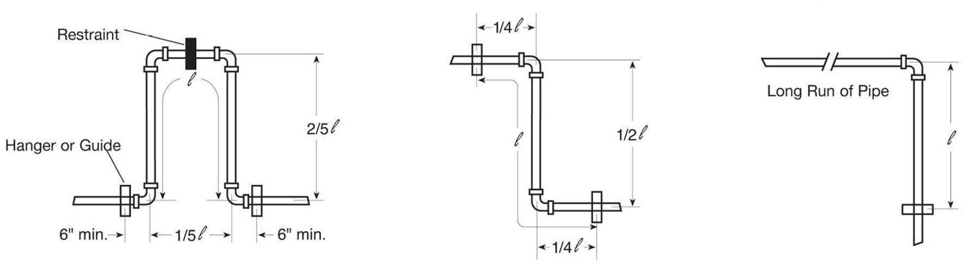
Expansion Loop and Offset Configurations
Hangers or guides should only be placed in the loop, offset or change of direction as indicated above. Piping supports should restrict lateral movement
and should direct axial movement into the expansion loop.
Thermal Expansion — Sample Calculation
Example: How much expansion can be expected in a 200 ft. run of 2" GF Harvel Fire Sprinkler CPVC pipe and how long should the expansion loop be to compensate for this expansion? (The expected temperature range will be from 40°F to 110°F.)
- First Find: ΔT = (Change in Temperature)
- ΔT = T2 - T1
- ΔT = 10°F - 40°F
- ΔT = 70°F
- To Find: ΔL = (Amount of Expansion in in. from Table III.)
- ΔL = DL of 160 ft. with a DT of 70°F + DL of 40 ft. with a DT of 70°F
- ΔL = 4.57” + 1.14”
- ΔL = 5.71”
— OR —
- ΔL = 12eL (ΔT)
- e = 3.4 x 10⁻⁵ (from Table II.)
- L = Length of Run in Feet
- ΔT = Change in Temperature in °F
- ΔL = 12 x .000034 x 200 x 70
- ΔL = 5.71”
- $$/ = \sqrt{ {3ED(ΔL)} \over 2S}$$
- / = Length of Expansion Loop in inches
- E = Modulus of Elasticity at 100°F (Table I)
- D = Average O.D. of Pipe
- ΔL = Change in Length of Pipe Due to Change in Temperature (Table III)
- S = Working Stress at 100°F (Table I)
To find the length of the expansion loop or offset in inches
- $$/ = \sqrt{ {3ED(ΔL)} \over 2S}$$
- / = Length of Expansion Loop in inches
- E = Modulus of Elasticity at maximum temperature from Table I
- D = Average Outside Diameter of the pipe from Table IV
- S = Working Stress at maximum temperature from Table I
- ΔL = Change in Length of Pipe Due to Change in Temperature (Table III)
- $$/ = \sqrt{ {3 x 370,000 x 2.375 x 5.71} \over 2 x 1415}$$
-
- $$/ = \sqrt{ {5319} }$$
- / = 72.93"
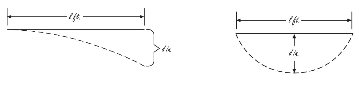
Table V
| Maximum Bending Deflections in Inches for Given Lengths of CPVC, SDR 13.5 (73°) |
Pipe Size (in.)
SDR 13.5 |
Length of Run ( l ) in Feet |
| 2 |
5 |
7 |
10 |
12 |
15 |
17 |
20 |
25 |
30 |
35 |
40 |
45 |
50 |
| Pipe Deflection ( d ) in Inches |
| ¾ |
1.3 |
7.8 |
15.4 |
31.3 |
45.1 |
70.5 |
90.6 |
124.4 |
195.9 |
282.1 |
383.9 |
- |
- |
- |
| 1 |
1.0 |
6.3 |
12.3 |
25.0 |
36.0 |
56.3 |
72.3 |
100.1 |
156.4 |
225.2 |
306.6 |
400.4 |
- |
- |
| 1-¼ |
0.8 |
5.0 |
9.7 |
19.8 |
28.5 |
44.6 |
57.3 |
79.3 |
123.9 |
178.4 |
242.8 |
317.2 |
401.4 |
- |
| 1-½ |
0.7 |
4.3 |
8.5 |
17.3 |
24.9 |
39.0 |
50.1 |
69.3 |
108.2 |
155.9 |
212.2 |
277.1 |
350.7 |
433.0 |
| 2 |
0.6 |
3.5 |
6.8 |
13.9 |
20.0 |
31.2 |
40.0 |
55.4 |
86.6 |
124.7 |
169.7 |
221.7 |
280.6 |
346.4 |
| 2-½ |
0.5 |
2.9 |
5.6 |
11.4 |
16.5 |
25.8 |
33.1 |
45.8 |
71.5 |
10.3.0 |
140.2 |
183.8 |
231.8 |
286.2 |
| 3 |
0.4 |
2.4 |
4.6 |
9.4 |
13.5 |
21.2 |
27.2 |
37.6 |
58.8 |
84.6 |
115.2 |
150.4 |
190.4 |
235.1 |
Table VI
| Maximum Snaking Deflections in Inches for Given Lengths of CPVC, SDR 13.5 at 73° |
Pipe Size (in.)
SDR 13.5 |
Length of Run ( l ) in Feet |
| 2 |
5 |
7 |
10 |
12 |
15 |
17 |
20 |
25 |
30 |
35 |
40 |
45 |
50 |
| Pipe Deflection ( d ) in Inches |
| ¾ |
0.3 |
2.0 |
3.8 |
7.8 |
11.3 |
17.6 |
22.6 |
31.3 |
49.0 |
70.5 |
96.0 |
125.4 |
158.7 |
195.9 |
| 1 |
0.3 |
1.6 |
3.1 |
6.3 |
9.0 |
14.1 |
18.1 |
25.0 |
39.1 |
56.3 |
76.6 |
100.1 |
126.7 |
156.4 |
| 1-¼ |
0.2 |
1.2 |
2.4 |
5.0 |
7.1 |
11.2 |
14.3 |
19.8 |
31.0 |
44.6 |
60.7 |
79.3 |
100.4 |
123.9 |
| 1-½ |
0.2 |
1.1 |
2.1 |
4.3 |
6.2 |
9.7 |
12.5 |
17.3 |
27.1 |
39.0 |
53.0 |
69.3 |
87.7 |
108.2 |
| 2 |
0.1 |
0.9 |
1.7 |
3.5 |
5.0 |
7.8 |
10.0 |
13.9 |
21.6 |
31.2 |
42.4 |
55.4 |
70.1 |
86.6 |
| 2-½ |
0.1 |
0.7 |
1.4 |
2.9 |
4.1 |
6.4 |
8.3 |
11.4 |
17.9 |
25.8 |
35.1 |
45.8 |
57.9 |
71.5 |
| 3 |
0.1 |
0.6 |
1.2 |
2.4 |
3.4 |
5.3 |
6.8 |
9.4 |
14.7 |
21.2 |
28.8 |
37.6 |
47.6 |
58.8 |
Read Less